DIY Neuroscience Kit Pro#
This is the advanced DIY Neuroscience Kit with Muscle BioAmp Shield - an EMG Shield for Arduino UNO! The shield offers multiple plug-and-play options, and additional data acquisition while the BioAmp EXG Pill enhances versatility by enabling the measurement of various biopotential signals, including EEG (brain), EOG (eyes), EMG (muscles), and ECG (heart). Start your journey of discovery, as you build exciting projects, develop HCI/BCI applications, and gain valuable insights.
DIY Neuroscience Kit Pro#
Contents of the kit#
Kit Contents |
Qty |
|---|---|
BioAmp EXG Pill |
1 |
BioAmp Bands |
3 |
BioAmp Cable |
1 |
Jumper Cables (set of 3) |
1 |
Skin Preparation Kit |
1 |
Electrode Gel |
1 |
Gel Electrodes |
24+100 |
Repositionable gel electrodes (3 pc) |
1 |
Arduino UNO R3/Arduino UNO R4 Minima |
1 |
Servo Claw |
1 |
Muscle BioAmp Shield Kit (With 1 BioAmp Cable, 6 STEMMA Cables, 9V snap cable, BioAmp AUX Cable, Muscle BioAmp Band, 24 gel electrodes, & Muscle BioAmp Shield) |
1 |
Click on the link below to see the unboxing of the kit:
Software requirements#
To use your DIY Neuroscience Kit Pro, you will need the softwares mentioned below. Instructions on how to use them are provided later in the guide.
Arduino IDE v1.8.19 (legacy IDE) (Download this to upload Chords arduino firmware to your development board)
Chords Web (Use this open-source web application to visualize your biopotential signals)
Visual Studio Code (or any other Code editor of your choice)
Python (To run Chords-Python script)
Chords Python (Use this open-source python script designed to record and visualize biopotential signals)
Note
The Chords Arduino firmware is identical for both Chords Web and Chords Python, so you only need to upload the code once, and you’re all set.
You can choose either Chords Web or Chords Python to record and visualize your biopotential signals based on your needs. If you’re curious, you can try both one at a time.
Using the kit#
DIY Neuroscience Kit Pro includes 2 biopotential sensors:
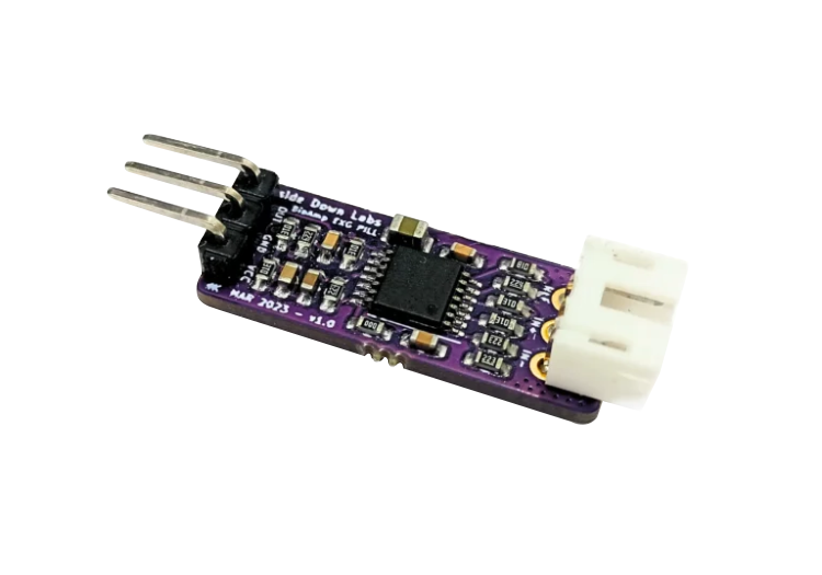
BioAmp EXG Pill (Assembled)
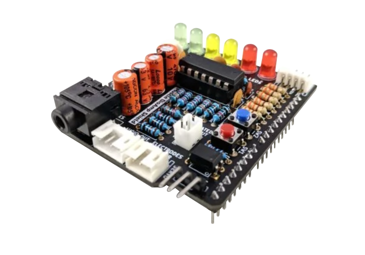
Muscle BioAmp Shield v0.3 (Assembled)
You can use these sensors either separately or connect them together to create a 2-channel EXG acquisition system wherein channel 1 can be used to record EMG signals and channel 2 allows you to record all the biopotential signals from your body (EMG, ECG, EOG, EEG).
Step 1: Using BioAmp EXG Pill#
BioAmp EXG Pill is a small, powerful analog-front-end (AFE) biopotential signal-acquisition board that can be paired with any microcontroller unit (MCU) or single-board computer (SBC) with an analog-to-digital converter (ADC) such as Arduino UNO & Nano, Adafruit QtPy, STM32 Blue Pill, BeagleBone Black, and Raspberry Pi Pico, to name just a few. It also works with any dedicated ADC, like the Texas Instruments ADS1115 and ADS131M0x, among others.
Note
Checkout the complete documentation on BioAmp EXG Pill which includes how to use the sensor, record various biopotential signals from your body (ECG, EMG, EOG, EEG) and make different HCI/BCI projects using it.
Step 2: Using Muscle BioAmp Shield#
Muscle BioAmp Shield is an all-in-one Arduino Uno ElectroMyography (EMG) shield for learning neuroscience with ease which is inspired from BackYard Brains (BYB) Muscle Spiker Shield and provides similar features like hobby servo output, user buttons, LED Bar, Audio output, and battery input. It is perfect for beginners as they can easily stack it on top of Arduino Uno to record, visualize and listen to their muscle signals to make amazing projects in the domain of Human-Computer Interface (HCI).
Note
Checkout the complete documentation on Muscle BioAmp Shield which includes how to use the sensor, record/visualise/listen muscle signals and make different HCI projects using it.
Step 3: Using the sensors together#
We believe that you have already gone through the documentation of BioAmp EXG Pill & Muscle BioAmp Shield using the links provided in step 1 and 2 respectively.
You have covered the basic steps till now including connections with the development board, skin preparation, electrodes placements, and recording the signals from your body.
Let’s become a PRO and create a 2-channel EXG aquisition system.
a. Connecting Muscle BioAmp Shield to MCU/ADC#
Stack the Muscle BioAmp Shield on top of your Arduino Uno properly.
b. Configure for ECG/EMG (optional)#
BioAmp EXG Pill is by default configured for recording EEG or EOG but if you want to record good quality ECG or EMG, then it is recommended to configure it by making a solder joint as shown in the image.
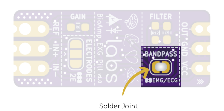
Configure BioAmp EXG Pill for EMG/ECG#
Note
Even without making the solder joint the BioAmp EXG Pill is capable of recording ECG or EMG but the signals would be more accurate if you configure it.
c. Connecting sensors together#
Connect the BioAmp EXG Pill to the A2 port of Muscle BioAmp Shield via 3-pin STEMMA cable which has JST PH 2.0mm connector on one end and 3 female jumpers on the other end.
Muscle BioAmp Shield |
BioAmp EXG Pill |
|---|---|
GND |
GND |
VCC |
5V |
A2 |
OUT |
d. Connecting electrode cables#
Connect one BioAmp cable to BioAmp EXG Pill and another BioAmp cable to Muscle BioAmp Shield by inserting the cable ends into the respective JST PH connectors as shown below:
e. Skin Preparation#
We’ll create a 2-channel EMG acquisition system and to do so, we’ll be using both the sensors to record EMG signals from the ulnar nerve of both the hands, Thus, prepare the skin accordingly.
Apply Nuprep Skin Preparation Gel on the skin surface where electrodes would be placed to remove dead skin cells and clean the skin from dirt. After rubbing the skin surface thoroughly, clean it with an alcohol wipe or a wet wipe.
For more information, please check out detailed step by step Skin Preparation Guide.
f. Electrodes placement#
We have 2 options to measure the EMG signals, either using the gel electrodes or using dry electrode based Muscle BioAmp Band. You can try both of them one by one.
Using gel electrodes#
Snap the BioAmp Cable connected to BioAmp EXG Pill to gel electrodes.
Peel the plastic backing from electrodes.
Place the IN+ and IN- cables on the left arm near the ulnar nerve & REF (reference) at the back of your left hand as shown below.
Now snap the BioAmp Cable connected to Muscle BioAmp Shield to gel electrodes.
Peel the plastic backing from electrodes.
Place the IN+ and IN- cables on the right arm near the ulnar nerve & REF (reference) at the back of your right hand as shown below.
Using Muscle BioAmp Band#
Snap the BioAmp Cable connected to BioAmp EXG Pill on Muscle BioAmp Band in a way such that IN+ and IN- are placed on the left arm near the ulnar nerve & REF (reference) on the far side of the band.
Snap the BioAmp Cable connected to Muscle BioAmp Shield on Muscle BioAmp Band in a way such that IN+ and IN- are placed on the right arm near the ulnar nerve & REF (reference) on the far side of the band.
Now put a small drop of electrode gel between the skin and metallic parts of BioAmp Cables to get the best results.
Tip
Visit the complete documentation on how to assemble and use the BioAmp Bands or follow the youtube video given below.
Tutorial on how to use the band:
Note
In this demonstration we are recording EMG signals from the ulnar nerve, but you can record EMG from other areas as well (biceps, triceps, legs, jaw etc) as per your project requirements. Just make sure to place the IN+, IN- electrodes on the targeted muscle and REF on a bony part.
g. Uploading the code#
Connect Arduino Uno to your laptop using the USB cable (Type A to Type B). Download the github repository given below:
Muscle BioAmp Arduino Firmware
Go to the folder 8_EMGScrolling, open the arduino sketch 8_EMGScrolling.ino in Arduino IDE.
Go to tools from the menu bar, select board option then select Arduino UNO. In the same menu,
select the COM port on which your Arduino Uno is connected. To find out the right COM port,
disconnect your Arduino UNO board and reopen the menu. The entry that disappears should be the
right COM port. Now upload the code.
Important
Make sure your laptop is not connected to a charger and sit 5m away from any AC appliances for best signal acquisition.
h. Testing the connections#
Go to tools from the menu bar, click on serial monitor to open it or click on the icon on the top right corner. Try flexing both of your arms one-by-one. The output values should be 0 at this point.
Press the SW1 button on Muscle BioAmp Shield. Now you’ll see green LED glowing on the LED bar. When you flex your right arm, you’ll get output value 1 on the serial monitor and red LED will glow. Similarly, when you flex your left arm, you’ll get output value 2 and yellow LED will glow.
i. Running python script#
Open Visual Studio Code, click on File > Open folder to open the folder 8_EMGScrolling.
Open the terminal, and ensure that the path is configured to the location of the requirement.txt file.
To install all the modules that are required to run the Python script, write the given command in the terminal:
pip install -r requirements.txt
Open EMG_Scroll.py and change the COM Port in the code (line 14) as per the COM Port you selected in Arduino IDE. Save the file by clicking CTRL + S.
# Arduino serial port interface
ser = serial.Serial('COM12', 115200, timeout=1)
Run the Python script EMG_Scroll.py by writing the given command in the terminal:
python EMG_Scroll.py
j. Scrolling using EMG signals#
Press the SW1 button on Muscle BioAmp Shield again.
In the terminal, you will see Move Now prompt. When you flex your right arm, you’ll see UP in the terminal. Similarly, when you move your left arm, you’ll see DOWN in the terminal.
Now, open youtube shorts on your laptop and start scrolling using your muscle signals.
Note
What’s happening in the background? Whenever an EMG signal is detected, it acts as a trigger to emulate UP or DOWN key on the keyboard.
k. Calibrating the code#
Changes in Arduino Sketch
Modify the threshold values on lines 73 and 74. Threshold 1 is for the EMG signals recorded from the Muscle BioAmp Shield, and threshold 2 is for the EMG signals recorded from the BioAmp EXG Pill.
Uncomment line 71 in the Arduino code and navigate to Tools > Serial Plotter. You’ll see two plots showing the EMG signals of both of your arms. Flex your right arm and observe the peak value on the y-axis. If the peak value is around 240, you can set threshold 1 anywhere between 150 to 200. The lower the threshold value, the easier it is to trigger the output as UP or DOWN, and vice versa. Repeat the process to determine the threshold 2 value for your left arm.
After setting the thresholds, comment out line 71.
Changes in Python script
Adjust the latency value on line 51. A higher latency value will make the output less responsive, requiring you to flex and hold longer to scroll through the screen. A lower latency value will make the output more responsive, allowing you to scroll through the screen more easily.
l. Conclusion#
This was just a demonstration to show you how both the sensors (BioAmp EXG Pill & Muscle BioAmp Shield) can be used together to create a 2-channel EXG acquisition system. In this project, we used BioAmp EXG Pill to record EMG signals, but it can also be used to record other biopotential signals as well like ECG, EOG, or EEG.
Some project ideas#
Upside Down Labs on Instructables:
1. Projects made using BioAmp EXG Pill#
1. Projects made using Muscle BioAmp Shield#
1. Projects made using the sensors together#
These are some of the project ideas but the possibilities are endless. So create your own Human Computer Interface (HCI) and
Brain Computer Interface (BCI) projects and share them with us at contact@upsidedownlabs.tech.