Welcome to Upside Down Labs docs site!

DIY Neuroscience Kit Basic#

Overview#

This kit is perfect for students, researchers and hobbyists alike who want to start exploring neuroscience. Whether it’s studying brain waves, monitoring heart rhythms, analyzing muscle movements, or tracking eye movements, this DIY kit provides an accessible and educational platform for understanding the complexities of human physiology and developing practical applications in the fields of human-computer interaction, and beyond.
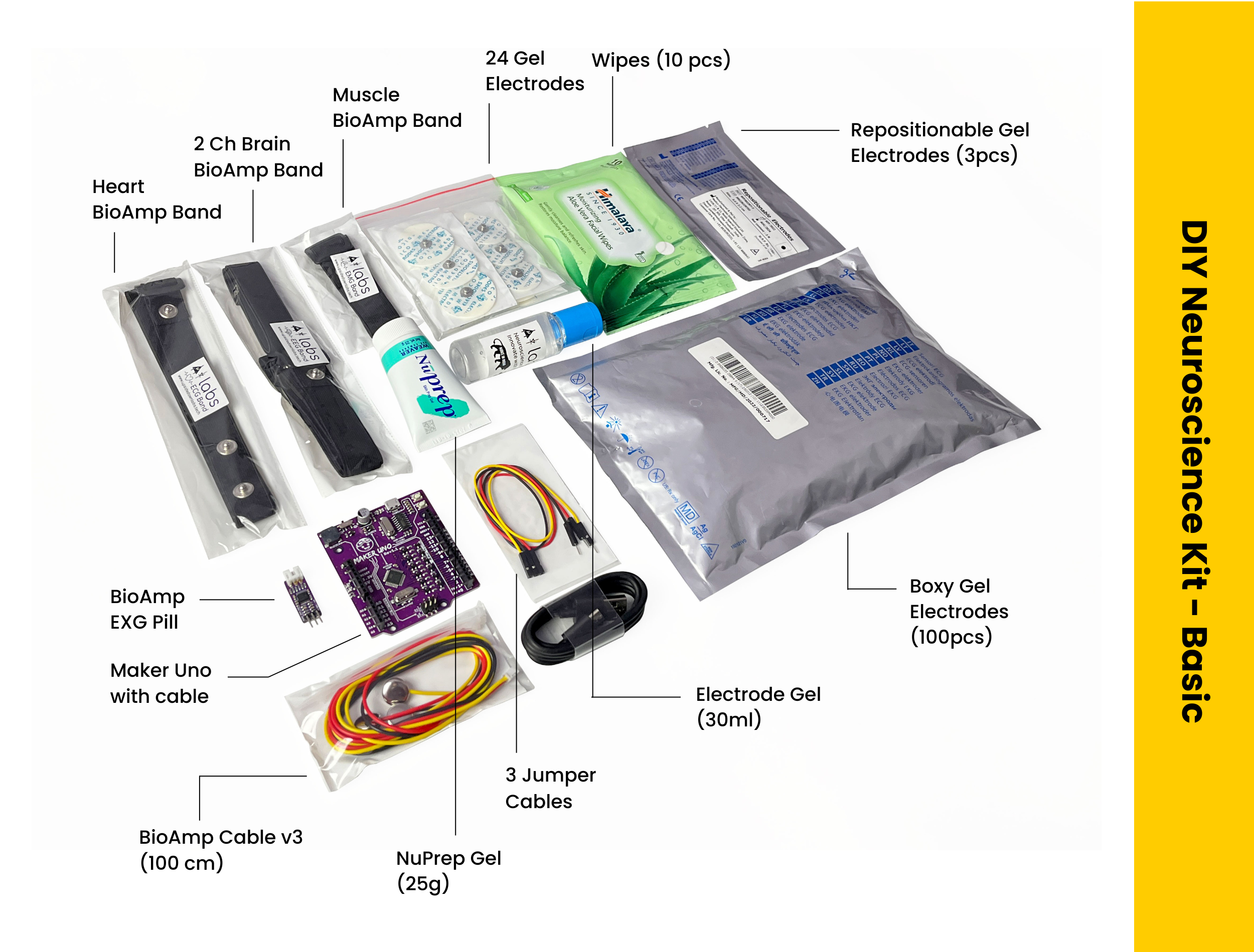
../../../_images/diy-neuroscience-kit-basic.png

Contents of the kit#

From development board (Maker UNO), BioAmp EXG Pill, BioAmp cable v3, jumper cables, gel electrodes, dry electrode-based BioAmp bands to skin preparation kit, this includes everything that you need to get started with your awesome HCI/BCI project.

../../../_images/kit-contents5.png

Unboxing the kit:

Software requirements#

  • Before you start using the kit, please download Arduino IDE v1.8.19 (legacy IDE). Using this you’ll be able to upload the arduino sketches in Maker UNO and visualise the data on your laptop.

../../../_images/arduino-ide.png
  • Download Backyard Brains’ Spike Recorder according to the operating system you are using (Windows, OSX, Linux).

../../../_images/byb.png

Using the kit#

This kit is made in a way so that even beginners can use it and get started with recording biopotential signals from their body to explore the field of neuroscience by making HCI/BCI projects.

Step 1 (optional): Configure for EMG/ECG#

../../../_images/configuration-emg-ecg.png

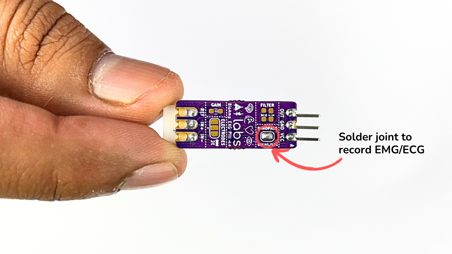
BioAmp EXG Pill is by default configured for recording EEG or EOG, so if you are recording any of the two signals you can skip this step. But if you want to record good quality ECG or EMG, then it is recommended to configure it by making a solder joint as shown in the image above.

Note

Even without making the solder joint the BioAmp EXG Pill is capable of recording ECG or EMG as well but the signals would be more accurate if you configure it.

Step 2: Connect Maker UNO#

../../../_images/connection-with-maker-uno.png

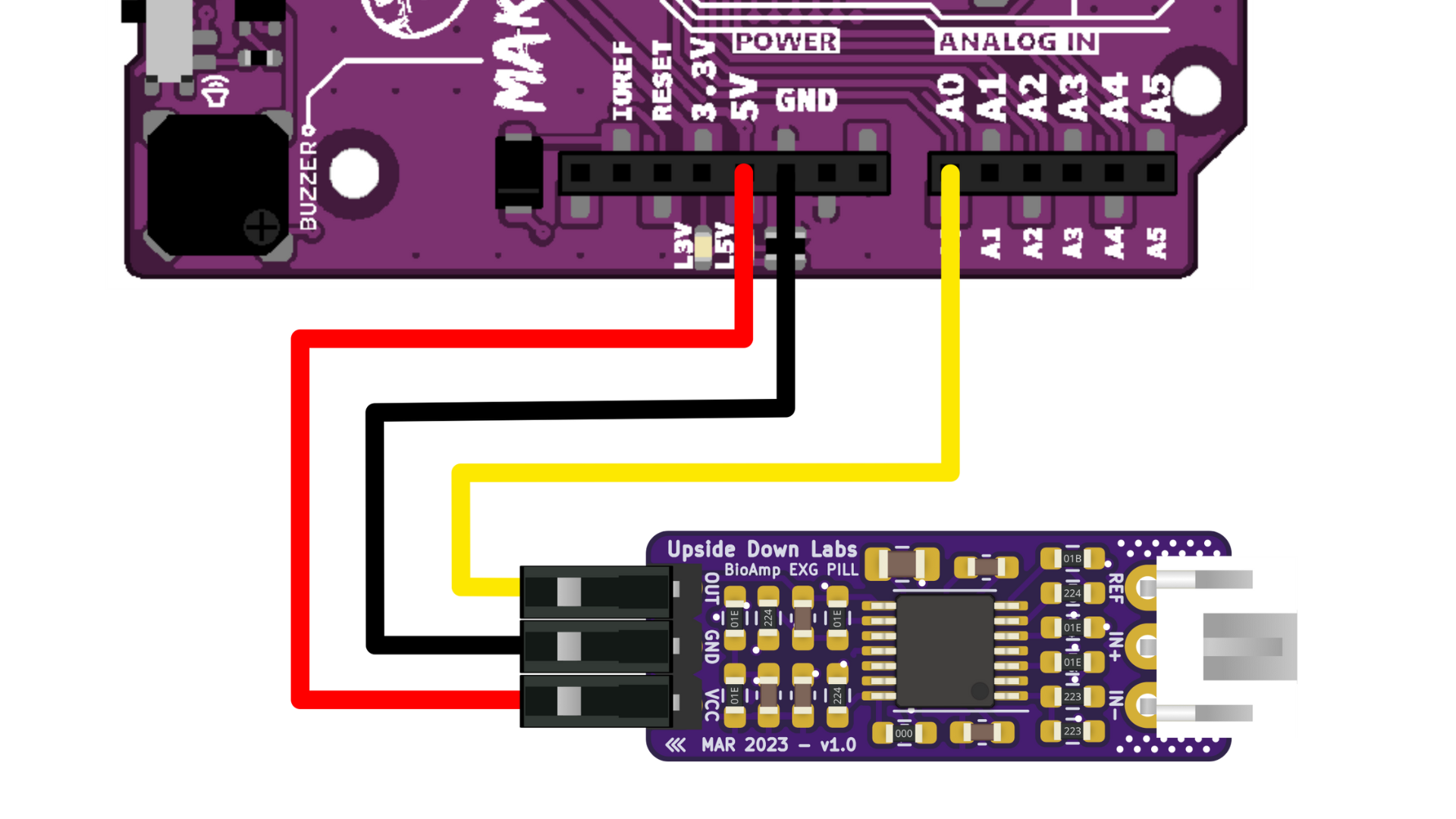
Connect VCC to 5V, GND to GND, and OUT to Analog pin A0 of your Maker UNO via jumper cables provided by us. If you are connecting OUT to any other analog pin, then you will have to change the INPUT PIN in the arduino sketch accordingly.

Warning

Take precautions while connecting to power, if power pins (GND & VCC) are to be swapped, your BioAmp EXG Pill will be fried and it’ll become unusable (DIE).

Step 3: Connecting electrode cable#

../../../_images/bioamp-cable.png

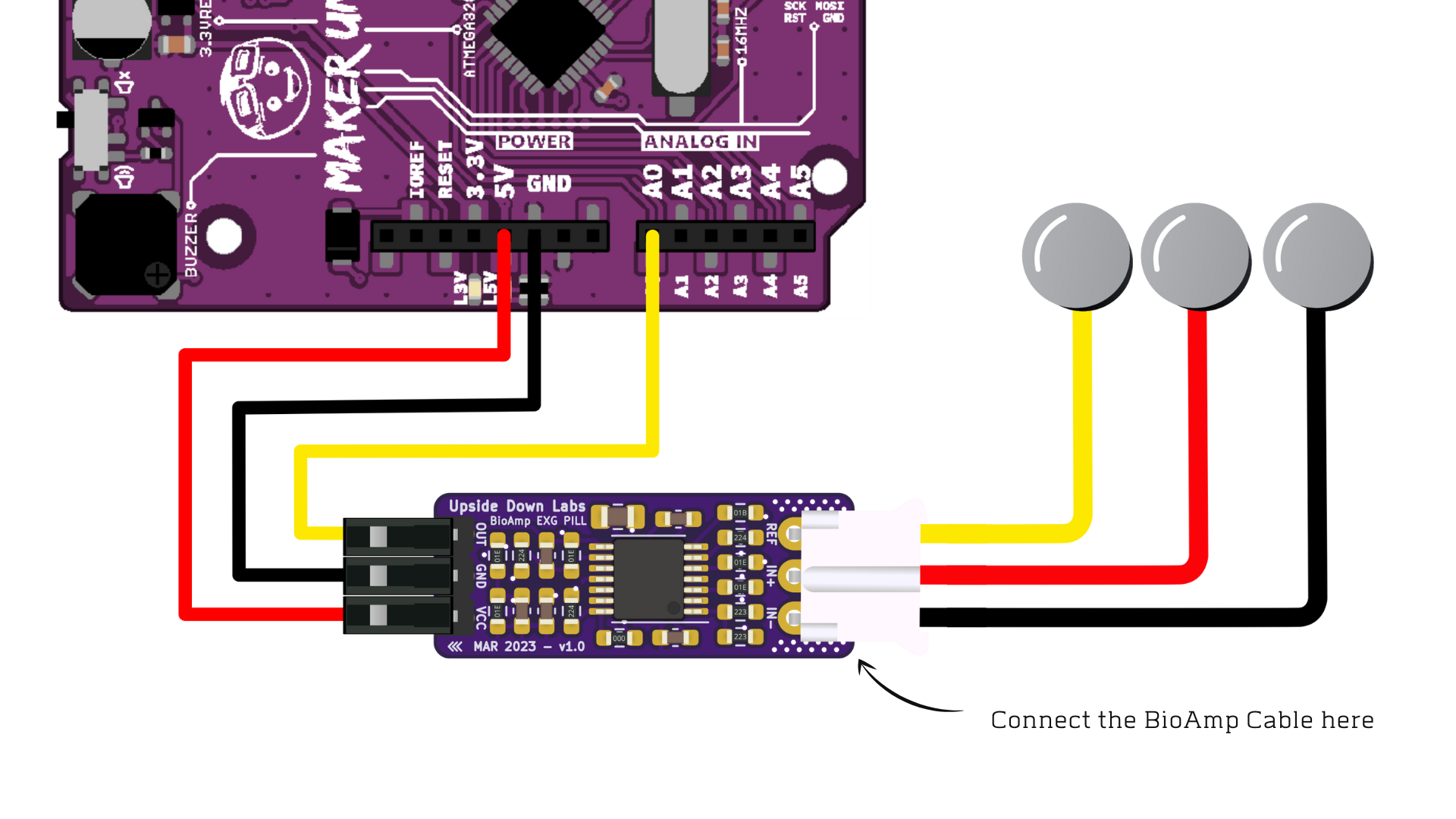
Connect the BioAmp cable to BioAmp EXG Pill by inserting the cable end in the JST PH connector as shown above.

Step 4: Skin Preparation#

Apply Nuprep Skin Preparation Gel on the skin surface where electrodes would be placed to remove dead skin cells and clean the skin from dirt. After rubbing the skin surface thoroughly, clean it with an alcohol wipe or a wet wipe.

For more information, please check out detailed step by step Skin Preparation Guide.

Step 5: Measuring EMG (ElectroMyoGraphy)#

Electrodes placement#

We have 2 options to measure the EMG signals, either using the gel electrodes or using dry electrode based Muscle BioAmp Band. You can try both of them one by one.

  • Using gel electrodes:

  1. Connect the BioAmp cable to gel electrodes,

  2. Peel the plastic backing from electrodes

  3. Place the IN+ and IN- cables on the arm near the ulnar nerve & REF (reference) at the back of your hand as shown in the connection diagram.

../../../_images/emg1.png
  • Using Muscle BioAmp Band:

  1. Connect the BioAmp cable to Muscle BioAmp Band in a way such that IN+ and IN- are placed on the arm near the ulnar nerve & REF (reference) on the far side of the band.

  2. Now put a small drop of electrode gel between the skin and metallic part of BioAmp cable to get the best results.

    Tutorial on how to use the band:

Note

In this demonstration we are recording EMG signals from the ulnar nerve, but you can record EMG from other areas as well (biceps, triceps, legs, jaw etc) as per your project requirements. Just make sure to place the IN+, IN- electrodes on the targeted muscle and REF on a bony part.

Uploading the code#

Connect the Maker Uno to your laptop using the USB cable (Type A to Type B). Copy paste any one of the Arduino Sketches given below in Arduino IDE v1.8.19 that you downloaded earlier:

EMG Filter: upsidedownlabs/Muscle-BioAmp-Arduino-Firmware

EMG Envelope: upsidedownlabs/Muscle-BioAmp-Arduino-Firmware

Go to tools from the menu bar, select board option then select Arduino UNO. In the same menu, select the COM port on which your Maker Uno is connected. To find out the right COM port, disconnect your Maker UNO board and reopen the menu. The entry that disappears should be the right COM port. Now upload the code, & open the serial plotter from the tools menu to visualize the EMG signals.

After opening the serial plotter make sure to select the baud rate to 115200.

Warning

Make sure your laptop is not connected to a charger and sit 5m away from any AC appliances for best signal acquisition.

Visualizing the EMG signals#

Now flex your arm to visualize the muscle signals in real time on your laptop.

../../../_images/EMGEnvelop1.jpg

Step 6: Measuring ECG (ElectroCardioGraphy)#

Electrodes placement#

We have 2 options to measure the ECG signals, either using the gel electrodes or using dry electrode based Heart BioAmp Band. You can try both of them one by one.

  • Using gel electrodes:

  1. Connect the BioAmp cable to gel electrodes

  2. Peel the plastic backing from electrodes

  3. Place the IN- cable on the left side, IN+ in the middle and REF (reference) on the far right side as shown in the diagram.

../../../_images/ecg1.png
  • Using Heart BioAmp Band:

  1. Wear the band as depicted in the video tutorial given below

  2. Place the IN- cable on the left side, IN+ in the middle and REF (reference) on the far right side.

  3. Now put a small drop of electrode gel between the skin and metallic part of BioAmp cable to get the best results.

Tutorial on how to use the band:

Uploading the code#

Connect the Maker Uno to your laptop using the USB cable (Type A to Type B). Copy paste the Arduino Sketch given below in Arduino IDE v1.8.19 that you downloaded earlier:

ECG Filter: upsidedownlabs/Heart-BioAmp-Arduino-Firmware

Go to tools from the menu bar, select board option then select Arduino UNO. In the same menu, select the COM port on which your Maker Uno is connected. To find out the right COM port, disconnect your Maker UNO board and reopen the menu. The entry that disappears should be the right COM port. Now upload the code, & open the serial plotter from the tools menu to visualize the EMG signals.

After opening the serial plotter make sure to select the baud rate to 115200.

Warning

Make sure your laptop is not connected to a charger and sit 5m away from any AC appliances for best signal acquisition.

Visualizing the ECG signals#

../../../_images/bioamp-Exg-Pill-ECG1.jpg

Step 7: Measuring EOG (ElectroOculoGraphy)#

Electrodes placement#

We have 2 ways to measure the EOG signals, either record the horizontal eye movement or the vertical eye movement. You can one by one record both the signals.

  • Horizontal EOG recording:

../../../_images/eog-horizontal1.png
  1. Connect the BioAmp cable to gel electrodes.

  2. Peel the plastic backing from electrodes.

  3. Place the IN- cable on the right side of the eye, IN+ on the left side of the eye and REF (reference) at the bony part, on the back side of your earlobe as shown in the diagram above.

  • Vertical EOG recording:

../../../_images/eog-vertical1.png
  1. Connect the BioAmp cable to gel electrodes.

  2. Peel the plastic backing from electrodes.

  3. Place the IN- & IN+ cables above and below the eye respectively and REF (reference) at the bony part, on the back side of your earlobe as shown in the diagram above.

Uploading the code#

Connect the Maker Uno to your laptop using the USB cable (Type A to Type B). Copy paste the Arduino Sketch given below in Arduino IDE v1.8.19 that you downloaded earlier:

EOG Filter: upsidedownlabs/Eye-BioAmp-Arduino-Firmware

Go to tools from the menu bar, select board option then select Arduino UNO. In the same menu, select the COM port on which your Maker Uno is connected. To find out the right COM port, disconnect your Maker UNO board and reopen the menu. The entry that disappears should be the right COM port. Now upload the code, & open the serial plotter from the tools menu to visualize the EMG signals.

After opening the serial plotter make sure to select the baud rate to 115200.

Warning

Make sure your laptop is not connected to a charger and sit 5m away from any AC appliances for best signal acquisition.

Visualizing the EOG signals#

../../../_images/bioamp-exg-pill-eog1.jpg

Step 8: Measuring EEG (ElectroEncephaloGraphy)#

Let’s understand the electrode placements before moving forward in this project. For recording EEG from different parts of the brain, you have to place the electrodes according to the International 10-20 system for recording EEG.

../../../_images/10-20-system.png

Electrodes placement#

We have 2 options to measure the EEG signals, either using the gel electrodes or using dry electrode based Brain BioAmp Band. You can try both of them one by one.

  • Using gel electrodes to record from prefrontal cortex part of brain:

../../../_images/eeg1.png
  1. Connect the BioAmp cable to gel electrodes.

  2. Peel the plastic backing from electrodes.

  3. Place the IN+ and IN- cables on Fp1 and Fp2 as per the International 10-20 system & REF (reference) at the bony part, on the back side of your earlobe as shown above.

  • Using Brain BioAmp Band to record from prefrontal cortex part of brain:

  1. Connect the BioAmp cable to Brain BioAmp Band in a way such that IN+ and IN- are placed on Fp1 and Fp2 as per the International 10-20 system.

  2. In this case, the REF (reference) should be connected using gel electrode. So connect the reference of BioAmp cable to the gel electrode, peel the plastic backing and place it at the bony part, on the back side of your earlobe.

  3. Now put a small drop of electrode gel on the dry electrodes (IN+ and IN-) between the skin and metallic part of BioAmp cable to get the best results.

Note

Similarly you can use the band to record EEG signals from the visual cortex part of brain by placing the dry electrodes on O1 and O2 instead of Fp1 and Fp2. Everything else will remain the same.

Tutorial on how to use the band:

Uploading the code#

Connect the Maker Uno to your laptop using the USB cable (Type A to Type B). Copy paste the Arduino Sketch given below in Arduino IDE v1.8.19 that you downloaded earlier:

Spike recorder arduino code

Go to tools from the menu bar, select board option then select Arduino UNO. In the same menu, select the COM port on which your Maker Uno is connected. To find out the right COM port, disconnect your Maker UNO board and reopen the menu. The entry that disappears should be the right COM port. Now upload the code.

Warning

Make sure your laptop is not connected to a charger and sit 5m away from any AC appliances for best signal acquisition.

Visualizing the EEG signals#

Open up your BackyardBrains Spike Recorder software. At first, it will monitor signals from your microphone. To change that, go to the settings by clicking the icon on the top left corner of the screen, select the COM port on which the Maker UNO is connected and click on connect.

../../../_images/spike-recorder-configurations.jpg

Mute the speakers and apply the 50Hz notch filter by clicking on the checkbox as shown in the screenshot above. You should set the low band pass filter to 1Hz and high bandpass filter to 40Hz as we are only recording the EEG signals which range between these frequencies.

Now everything is configured and connected. So close the settings window and start recording EEG signals.

../../../_images/bioamp-exg-pill-eeg.png

The signals that you can see on the screen right now are originating from prefrontal cortex part of your brain and propagating through all the layers to the surface of your skin.

To record these EEG signals, you have placed the electrodes on the forehead (Fp1 & Fp2), then BioAmp EXG Pill is amplifying those signals so that we can detect it and finally sending it to the ADC (Analog to Digital Convertor) of your Maker Uno. Ultimately the signals are being visualized in Spike Recorder software.

We hope everything is clear now and you understand how the signals are propagating from your brain to the screen of the laptop.

Features of Spike Recorder that you can explore:

  • Increase or decrease the scale of the Y axis by clicking on the + and - icons respecitively that is present on the left side of the graph.

  • Increase or decrease the X axis timescale by sliding up and down on the scroll wheel of the mouse.

  • Visualize the FFT graph by clicking on the FFT icon on top left size of the screen.

  • Record the data in .wav format by clicking the record icon on the top right corner. You can convert this data in any other format according to your project requirements.

  • Listen to the signals by clicking the volume icon on the top right corner. No don’t smile right now, that’s how your brain sounds like :P

Some Project Ideas#

Upside Down Labs on Instructables:

Recording EEG from visual cortex
Measuring heart rate
Detecting heart beats
Creating a drowsiness detector
Detecting eye blinks

These are some of the project ideas but the possibilities are endless. So create your own Human Computer Interface (HCI) and Brain Computer Interface (BCI) projects and share them with us at contact@upsidedownlabs.tech.