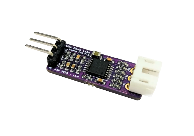
BioAmp EXG Pill#
v1.0
Overview#
BioAmp EXG Pill is a small, powerful analog-front-end (AFE) biopotential signal-acquisition board that can be paired with any microcontroller unit (MCU) or single-board computer (SBC) with an analog-to-digital converter (ADC) such as Arduino UNO & Nano, Adafruit QtPy, STM32 Blue Pill, BeagleBone Black, and Raspberry Pi Pico, to name just a few. It also works with any dedicated ADC, like the Texas Instruments ADS1115 and ADS131M0x, among others.
Note
It is recommended to use Arduino UNO R4 while recording biopotential signals since it has 14-bit ADC and can record the signals much accurately.
What makes it different?#
Record publication-quality biopotential signals like ECG, EMG, EOG, or EEG.
Small size (25.4 x 10.0mm) allows easy integration into mobile and space-constrained projects.
Powerful noise rejection makes it usable even when the device is close to the AC mains supply.
Any 1.5 mm diameter wire can be used as a strain-relieving electrode cable, making it very cost-effective.
Pair it with any MCU with an ADC. It is by default compatible with 5V but you can make it compatible with 3.3V as well using a voltage divider.
Configure the gain, band pass filter and electrode count according to your requirements.
Features & Specifications#
Operating Voltage |
3.3 V / 5 V |
Input Impedance |
10^12 ohm |
Compatible Hardware |
Any development board with an ADC (Arduino UNO & Nano, Adafruit QtPy, STM32 Blue Pill, BeagleBone Black, Raspberry Pi Pico, to name just a few) or any standalone ADC of your choice |
Bio-potential Signals |
EMG, ECG, EOG, EEG (configurable band-pass, by default configured for EEG & EOG) |
No. of channels |
1 |
Electrodes |
2 or 3 (By default configured for 3 electrodes) |
Dimensions |
25.4 x 10 mm |
Open Source |
Hardware + Software |
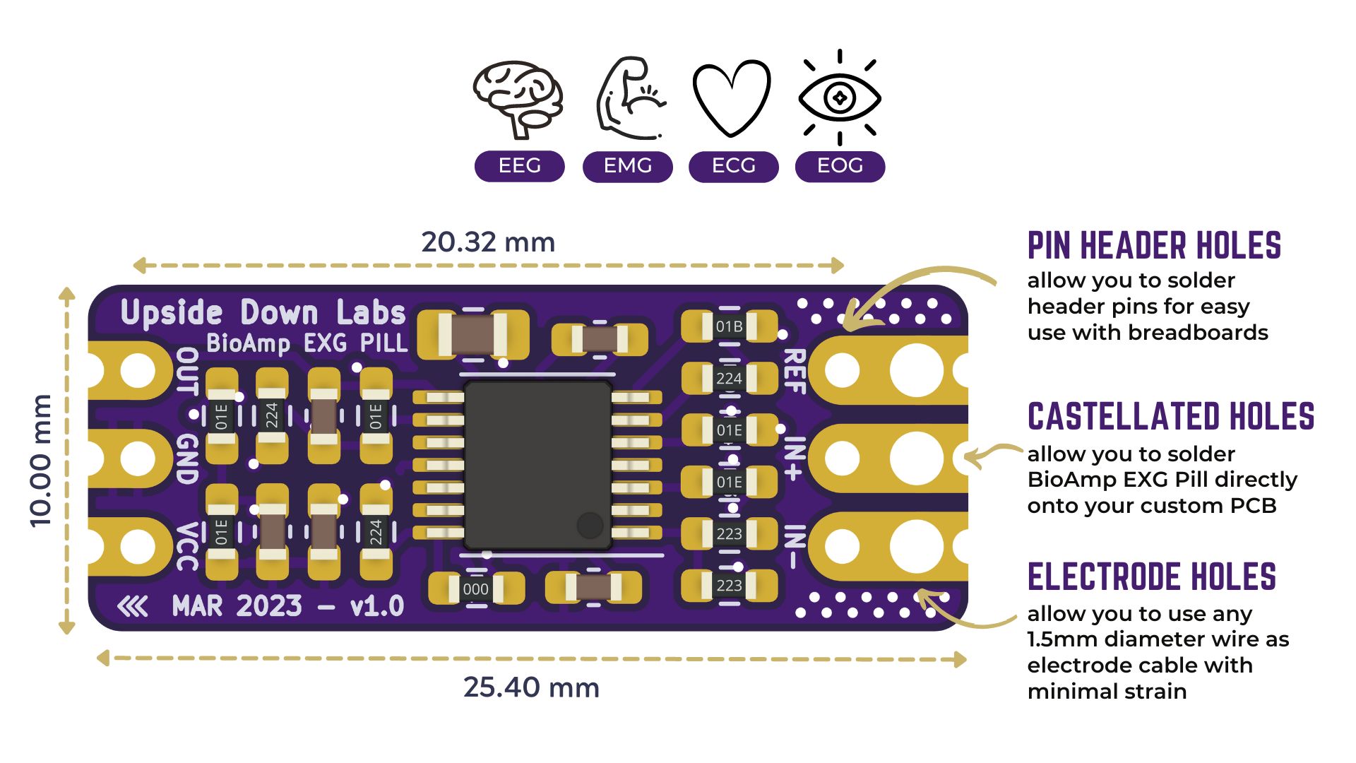
Board layout#
BioAmp EXG Pill’s elegant design allows it to be used in 3 ways:
Pin-header holes allow you to solder (berg strip) pin headers for easy use with a breadboard.
Castellated holes allow you to solder BioAmp EXG Pill directly onto a custom PCB that requires biopotential-amplification capabilities.
Electrode holes allow you to use any 1.5 mm diameter wire as an electrode cable with minimal strain.
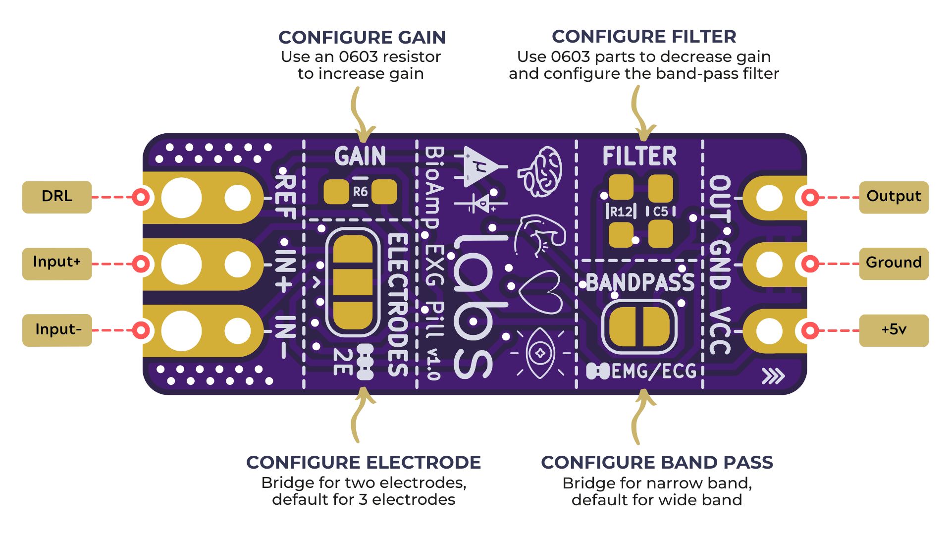
BioAmp EXG Pill is fully configurable#
Increase the gain of the instrumentation amplifier by using a 0603 resistor at
R6. Decrease gain and configure the bandpass filter by using 0603 parts atR12andC5. Band limiting is very useful for EOG and EEG recording. Also, the signal sometimes clips while recording an ECG with electrodes very close to the heart. Creating a solder jumper for a band-pass filter helps with that. By default, BioAmp EXG Pill is configured to record EEG and EOG but you can bridge the pads (below bandpass) with solder to make it configurable for EMG and ECG.The normal method of operation for best-quality signal amplification is to use 3 electrodes by default but you can bridge the pads (below electrodes) to make it configurable for 2 electrodes. The 2-electrode mode is specifically included for projects like heart (ECG) patches for HRV. It’s only supposed to be used with a battery-operated setup and is quite prone to high interference noise due to a lack of proper reference on the body (This option is not recommended for most operations)
Software Requirements#
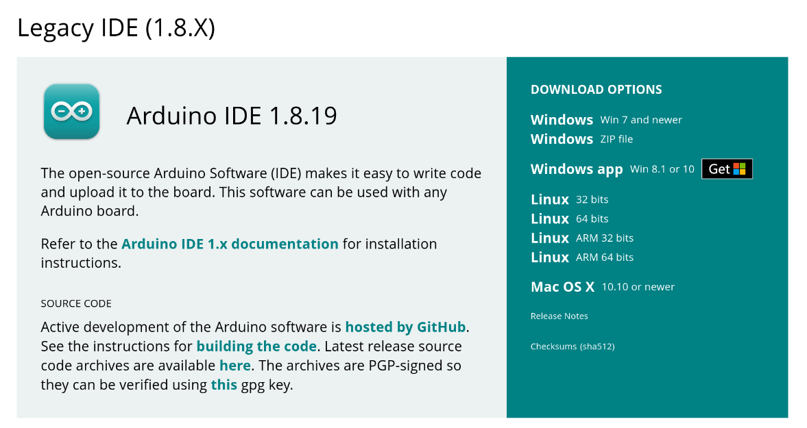
Arduino IDE
Latest Version (v2.3.8+): Arduino IDE Latest Version Download (Recommended for faster compilation and enhanced support for the latest Arduino UNO Development Boards)
Legacy Version (v1.8.19): Arduino IDE v1.8.19 (legacy IDE) Download (For Real-time signal visualization using a better built-in Serial Plotter)
Chords Web Visualizer
Use Chords Web, our custom web interface designed to visualize biopotential signals data directly in your browser. (Plug-and-play signal visualization directly in any modern web browser.)
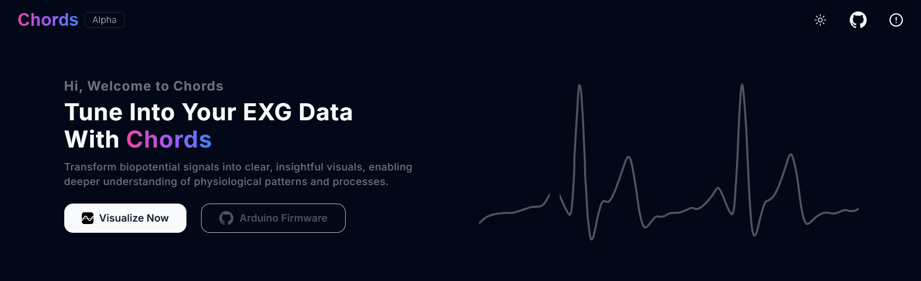
Chords Web Landing Page#
Using the Hardware#
If you have received the assembled BioAmp EXG Pill then you can skip the step 1 and move on to step 2.
Step 1: Solder Connectors#
Insert the provided BioAmp cable’s JST PH connector and header pins from top as shown in the image and solder them from below.
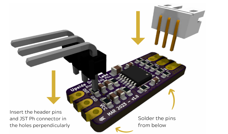
Soldering the connector & header pins on BioAmp EXG Pill#
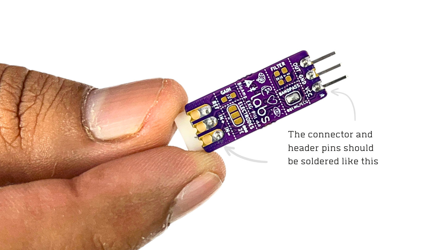
After soldering, BioAmp EXG Pill should look like this#
Step 2 (optional): Configure for ECG/EMG#
BioAmp EXG Pill is by default configured for recording EEG or EOG but if you want to record good quality ECG or EMG, then it is recommended to configure it by making a solder joint as shown in the image.
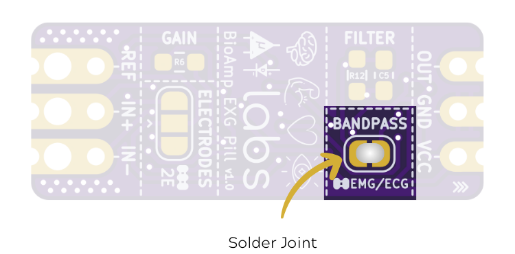
Note
Even without making the solder joint the BioAmp EXG Pill is capable of recording ECG or EMG but the signals would be more accurate if you configure it.
Step 3: Connect MCU/ADC#
Connect your BioAmp EXG Pill to your MCU/ADC as per the connection table shown below:
BioAmp EXG Pill |
MCU/ADC |
Function |
|---|---|---|
VCC |
5V / 3.3V |
Power Supply |
GND |
GND |
Ground |
OUT |
ADC Input |
Signal |
For all the examples provided, we are using the A0 pin of Arduino UNO R3. Connect your BioAmp to your MCU/ADC via jumper cables provided in the kit. If you are connecting OUT pin of BioAmp to any other analog pin (A0-A5) of Arduino UNO board, then you will have to change the INPUT PIN in the Arduino sketch accordingly.
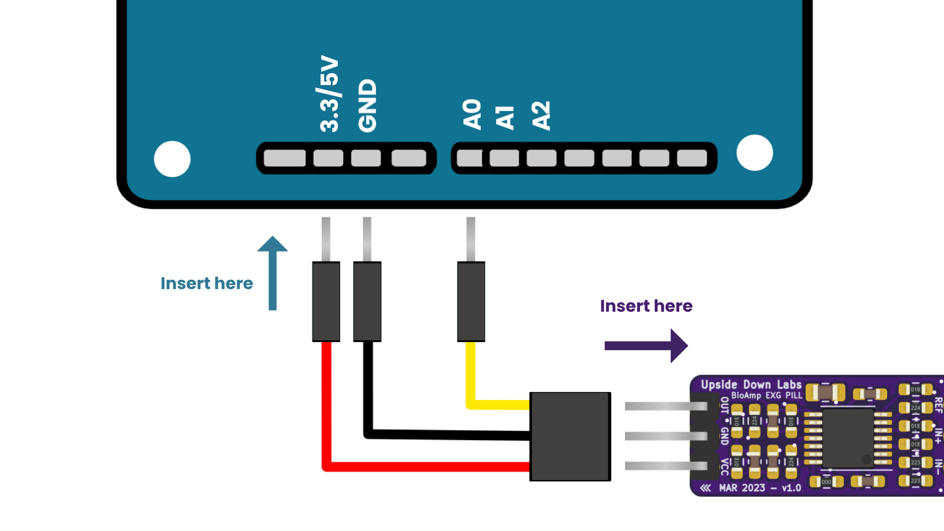
Wiring diagram for VCC, GND, and OUT Connections with Arduino UNO#
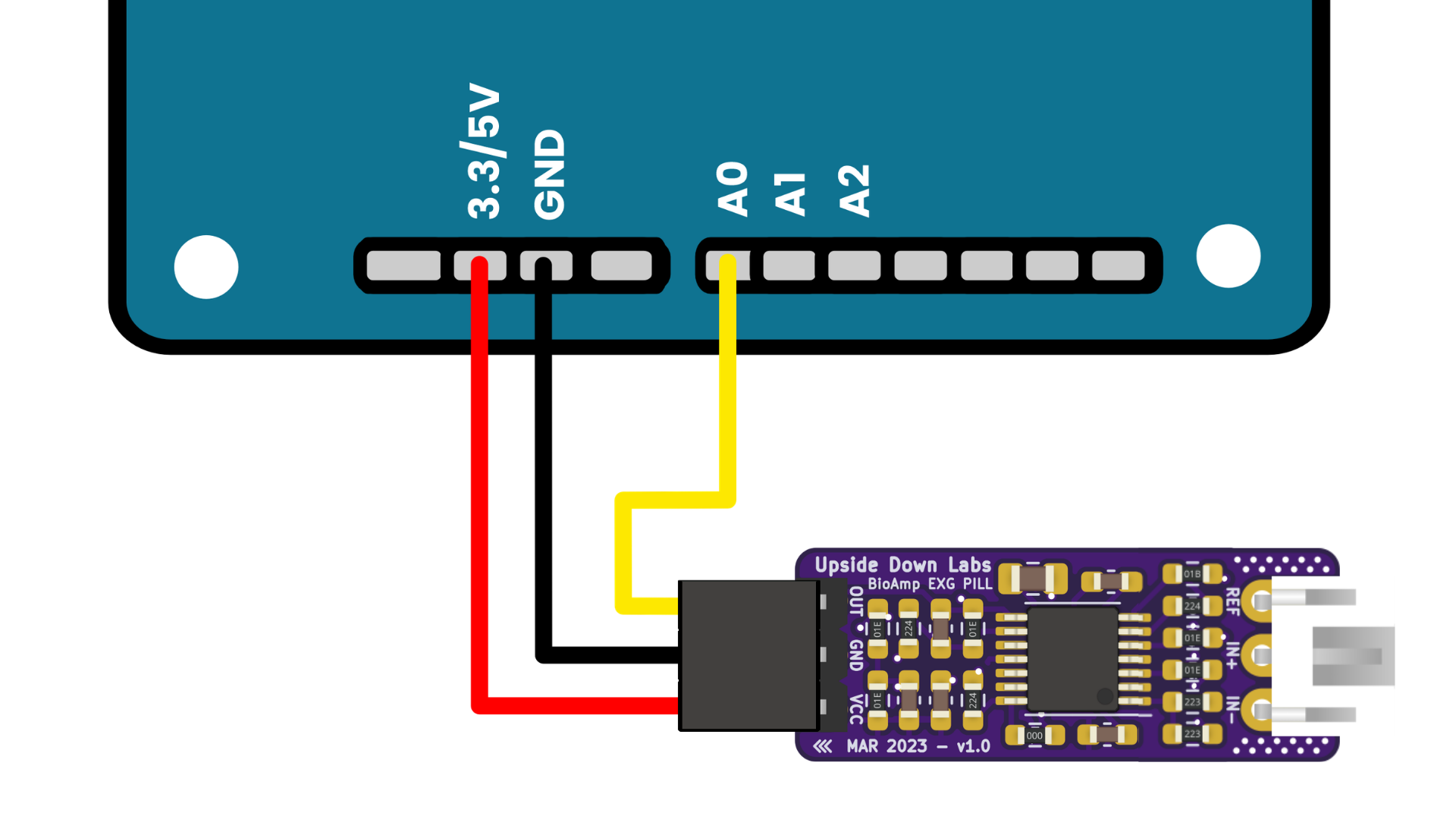
Connections with Arduino UNO Development Boards#
Warning
Take precautions while connecting to power, if power pins are to be swapped, your BioAmp EXG Pill will be fried and it’ll become unusable (DIE).
Step 4: Connecting electrode cable#
Connect the BioAmp cable to BioAmp EXG Pill by inserting the cable end in the JST PH connector as shown in the graphic below.
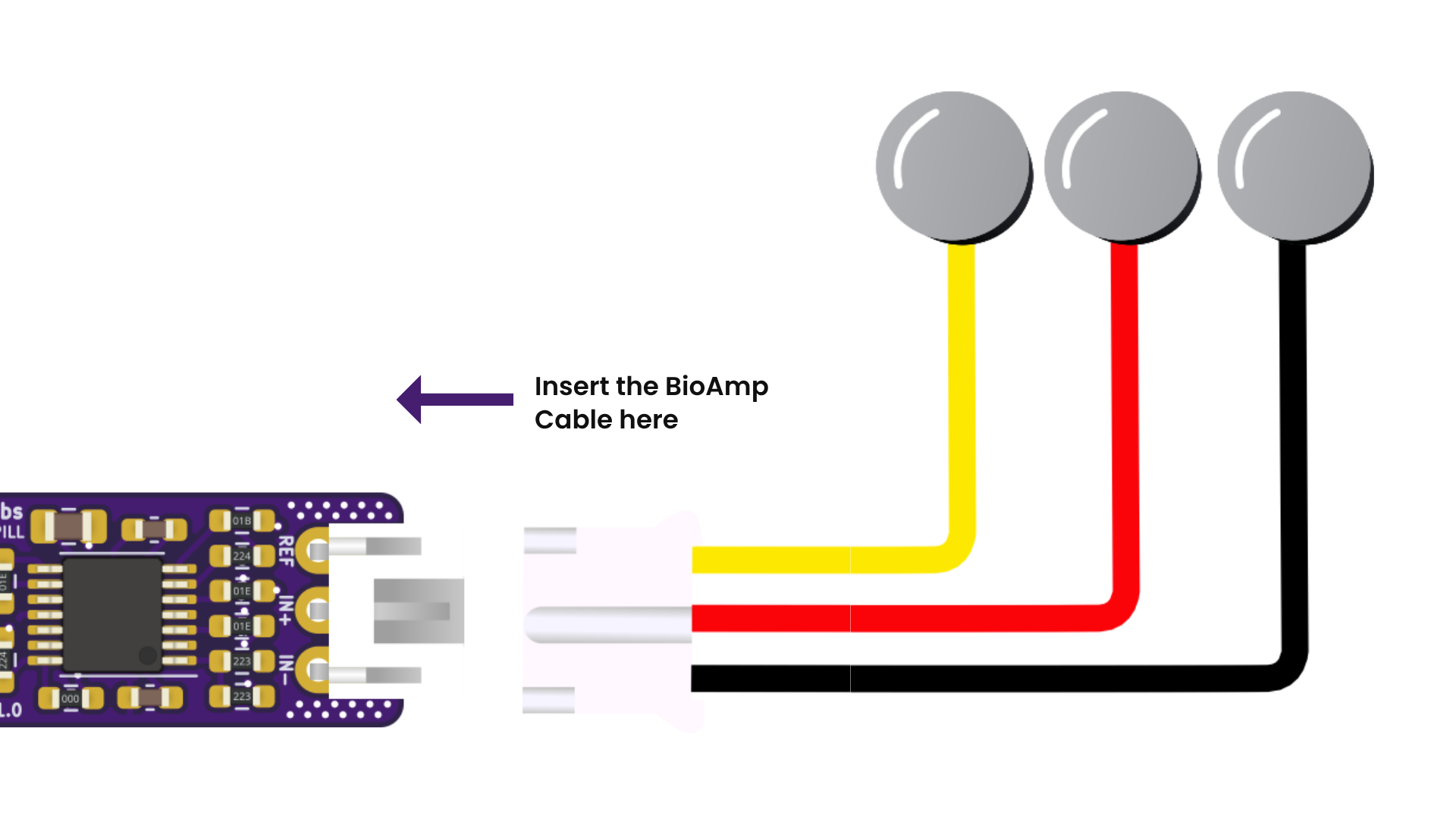
Connecting the BioAmp Cable v3 to the BioAmp EXG Pill#
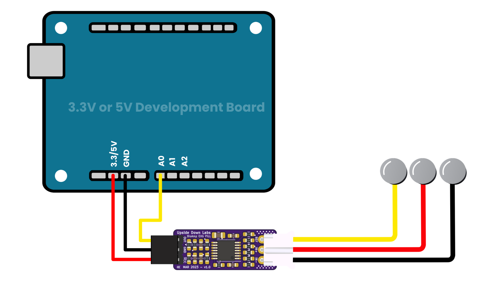
Complete assembly of BioAmp EXG Pill, Arduino, and BioAmp Cable v3#
Step 5: Skin Preparation#
Apply Nuprep Skin Preparation Gel on the skin surface where electrodes would be placed to remove dead skin cells and clean the skin from dirt. After rubbing the skin surface thoroughly, clean it with an alcohol wipe or a wet wipe.
For more information, please check out detailed step by step Skin Preparation Guide.
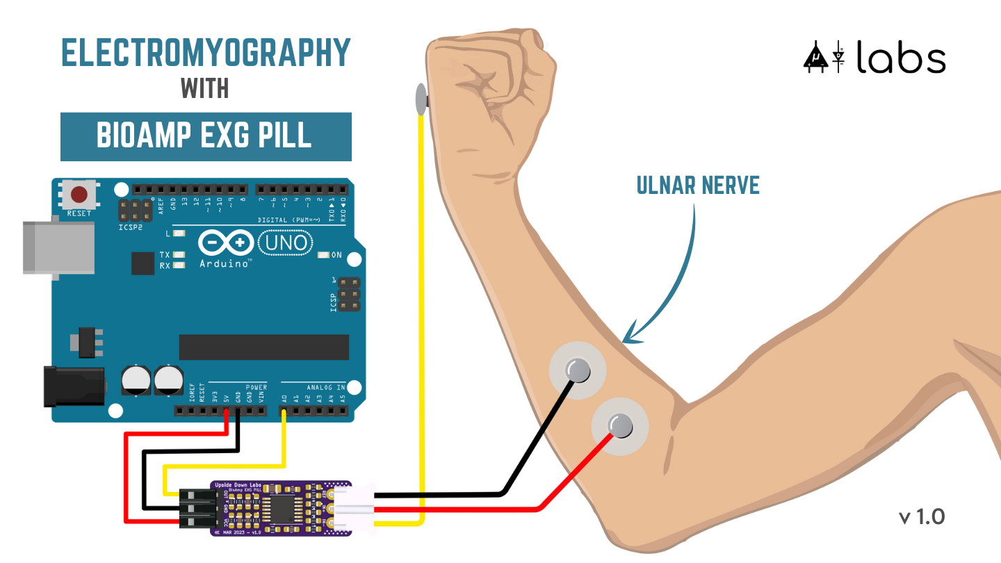
Step 6: Measuring ElectroMyoGraphy (EMG)#
Note
Electromyography (EMG) is a technique for evaluating and recording the electrical activity produced by skeletal muscles.
EMG is also used as a diagnostic procedure to assess the health of muscles and the nerve cells that control them (motor neurons).
EMG results can reveal nerve dysfunction, muscle dysfunction, or problems with nerve-to-muscle signal transmission.
Electrodes placement#
We have 2 options to measure the EMG signals, either using the gel electrodes or using dry electrode based Muscle BioAmp Band. You can try both of them one by one.
Using Gel electrodes:
Connect the BioAmp cable to gel electrodes,
Peel the plastic backing from electrodes
Place the IN+ and IN- cables on the arm near the ulnar nerve & REF (reference) at the back of your hand as shown in the connection diagram.
Using Muscle BioAmp Band:
Connect the BioAmp cable to Muscle BioAmp Band in a way such that IN+ and IN- are placed on the arm near the ulnar nerve & REF (reference) on the far side of the band.
Now put a small drop of electrode gel between the skin and metallic part of BioAmp cable to get the best results.
Tip
Visit the complete documentation on how to assemble and use the BioAmp Bands or follow the youtube video given below.
Tutorial on how to use the band:
Note
In this demonstration we are recording EMG signals from the ulnar nerve, but you can record EMG from other areas as well (biceps, triceps, legs, jaw etc) as per your project requirements. Just make sure to place the IN+, IN- electrodes on the targeted muscle and REF on a bony part.
Uploading the code#
Connect the Arduino UNO Development Board to your laptop using the USB cable. To upload the code use Arduino IDE latest version (v2.3.8+).
Choose and copy one of the following Arduino sketches based on your requirements:
Go to
Toolsmenu, navigate toBoard, and select Arduino UNO Development Board (UNO R3/ R4/ Minima/ WiFi or any other board).In the same menu, select the
Portto which your Arduino Uno is connected.Tip: To find the correct COM Port, disconnect your board and reopen the menu. The entry that disappears should be the right COM port.
Uploadthe code.
Tip
Check our complete documentation on How to upload the code.
Warning
For the best signal acquisition, ensure your laptop is not connected to a charger and maintain a distance of at least 5m from any AC appliances, read more about Tips for better signal acquisition.
Visualizing the EMG signals#
Using Chords Web
For visualizing the EMG signals, use Chords Web for quick and hassle-free real-time bio-potential signals visualization right from your browser, without installing any software.
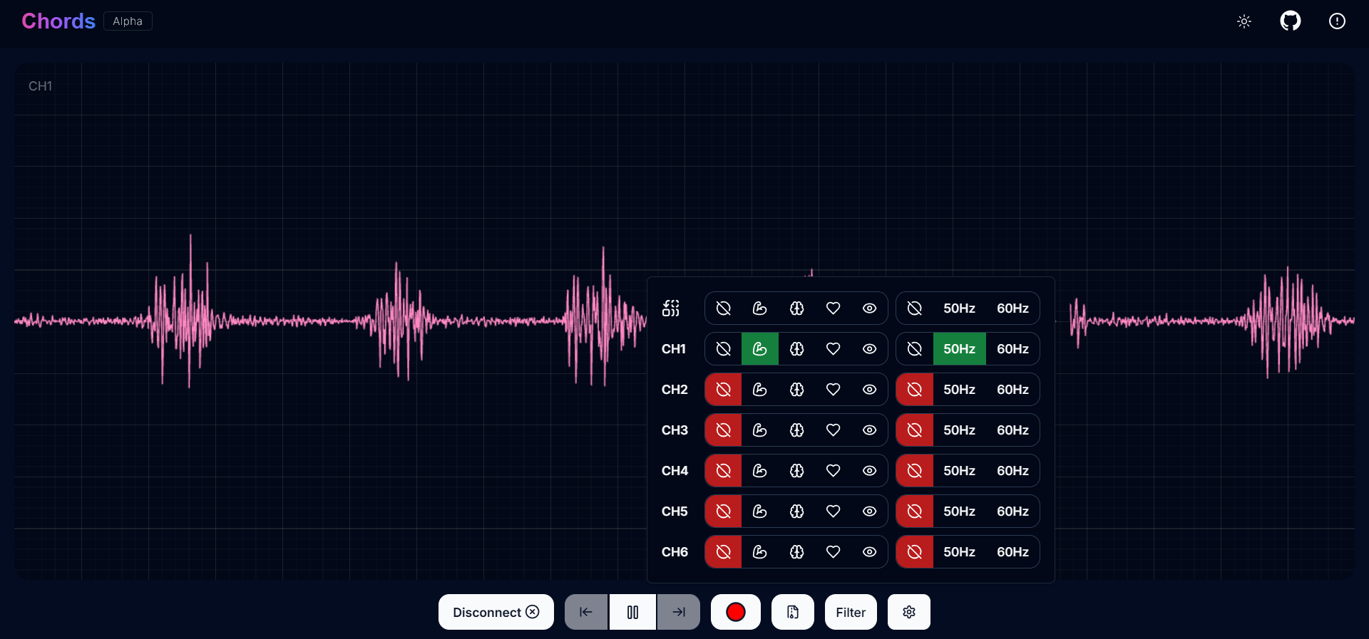
Visualizing EMG signals on Chords Web#
Now flex your arm to visualize the muscle signals in real time on your laptop.
Using Arduino legacy v1.8.19
To visualize the signal on Arduino v1.8.19 we will use inbuilt Serial Plotter:
Navigate to (
Tools>Board) and select your Development board or Arduino UNO Board (if not detected automatically).Open the Serial Plotter (
Tools>Serial PlotterorCtrl+Shift+L) to visualize the EMG signals.Once the Serial Plotter is open, ensure the baud rate is set to
115200.Now flex your arm to visualize the muscle signals in real time on your laptop.
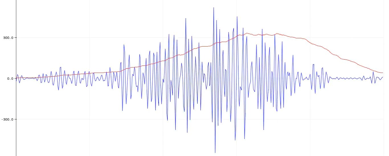
Visualizing EMG signals on Arduino IDE v1.8.x#
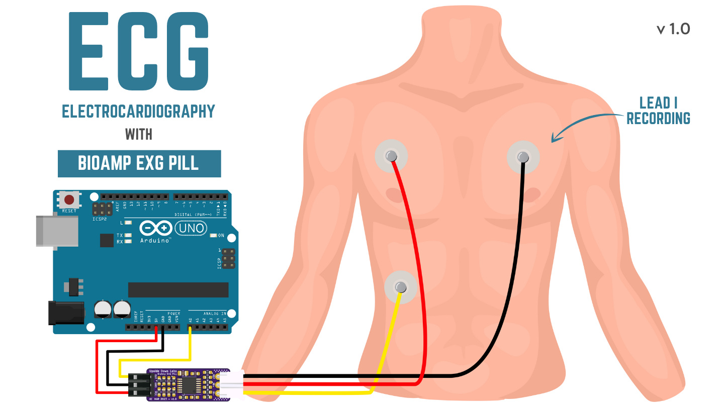
Step 6: Measuring ElectroCardioGraphy (ECG)#
Note
Electrocardiography (ECG) is the process of producing an electrocardiogram (ECG or EKG).
It is a graph of voltage versus time of the electrical activity of the heart using electrodes placed on the skin.
These electrodes detect the small electrical changes that are a consequence of cardiac muscle depolarization followed by repolarization during each cardiac cycle (heartbeat).
Electrodes placement#
We have 2 options to measure the ECG signals, either using the gel electrodes or using dry electrode based Heart BioAmp Band. You can try both of them one by one.
Using Gel electrodes:
Connect the BioAmp cable to gel electrodes
Peel the plastic backing from electrodes
Place the IN- cable on the left side, IN+ in the middle and REF (reference) on the far right side as shown in the diagram.
Using Heart BioAmp Band:
Wear the band as depicted in the video tutorial given below
Place the IN- cable on the left side, IN+ in the middle and REF (reference) on the far right side.
Now put a small drop of electrode gel between the skin and metallic part of BioAmp cable to get the best results.
Tip
Visit the complete documentation on how to assemble and use the BioAmp Bands or follow the youtube video given below.
Tutorial on how to use the band:
Uploading the code#
Connect the Arduino UNO Development Board to your laptop using the USB cable. To upload the code use Arduino IDE latest version (v2.3.8+).
Choose and copy one of the following Arduino sketches based on your requirements:
Go to
Toolsmenu, navigate toBoard, and select Arduino UNO Development Board (UNO R3/ R4/ Minima/ WiFi or any other board).In the same menu, select the
Portto which your Arduino Uno is connected.Tip: To find the correct COM Port, disconnect your board and reopen the menu. The entry that disappears should be the right COM port.
Uploadthe code.
Tip
Check our complete documentation on How to upload the code.
Warning
For the best signal acquisition, ensure your laptop is not connected to a charger and maintain a distance of at least 5m from any AC appliances, read more about Tips for better signal acquisition.
Visualizing the ECG signals#
Using Chords Web
For visualizing the ECG signals, use Chords Web for quick and hassle-free real-time bio-potential signals visualization right from your browser, without installing any software.
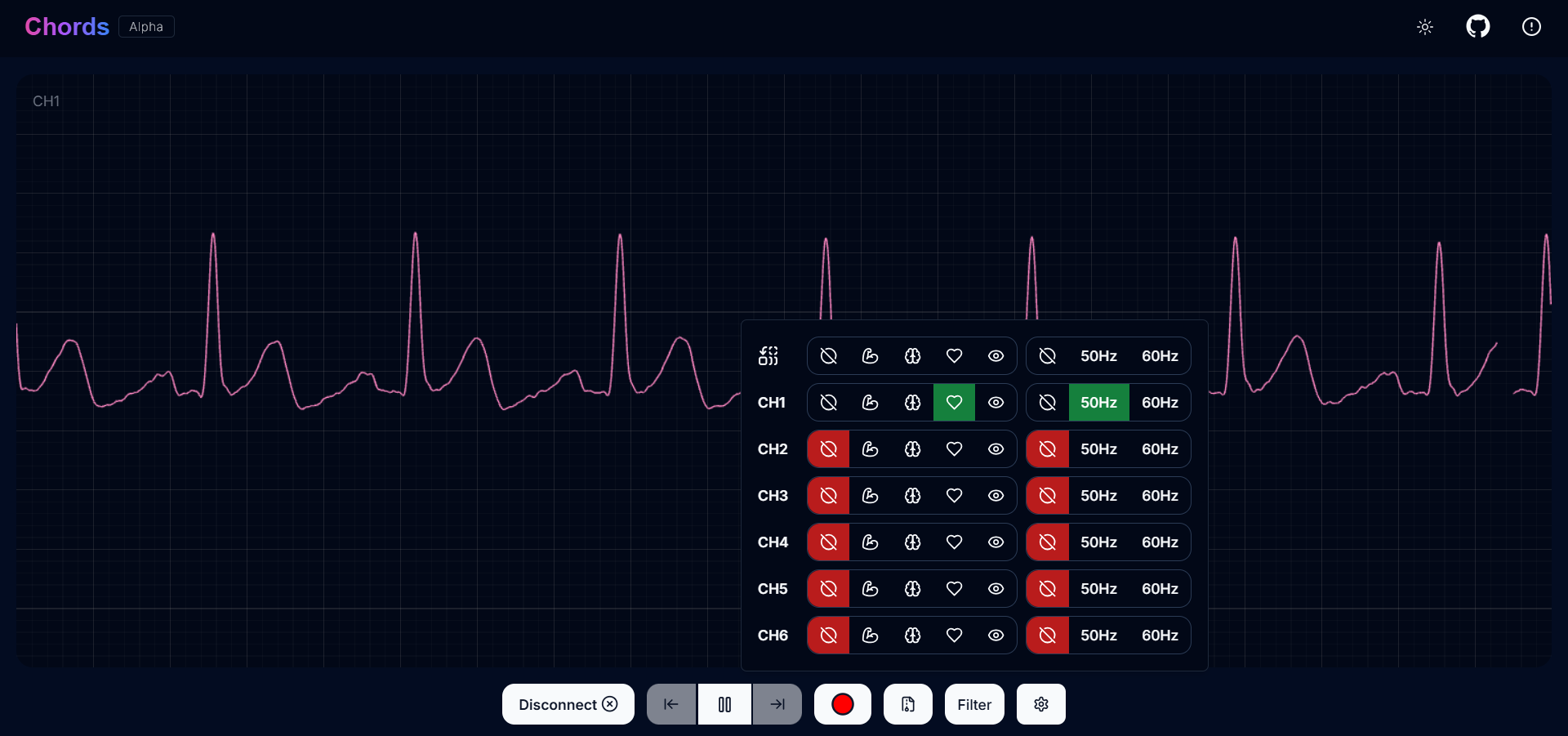
Visualizing ECG signals on Chords Web#
Sit back, relax and see your ECG signals in real time on your laptop.
Using Arduino legacy v1.8.19
To visualize the signal on Arduino v1.8.19 we will use inbuilt Serial Plotter:
Navigate to (
Tools>Board) and select your Development board or Arduino UNO Board (if not detected automatically).Open the Serial Plotter (
Tools>Serial PlotterorCtrl+Shift+L) to visualize the EMG signals.Once the Serial Plotter is open, ensure the baud rate is set to
115200.Now sit back, relax and see your ECG signals in real time on your laptop.
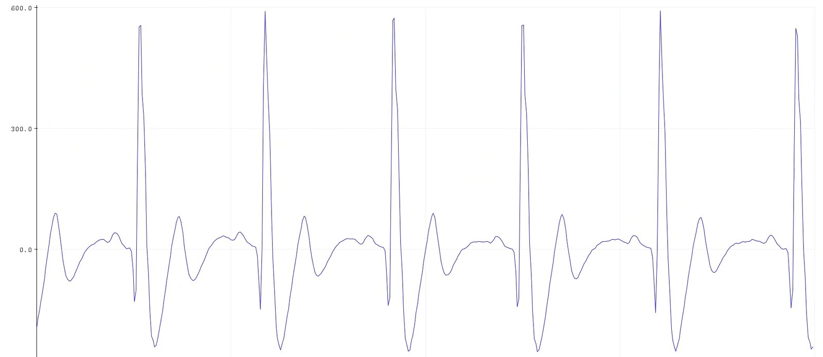
Visualizing ECG signals on Arduino IDE v1.8.x#
Step 7: Measuring Electrooculography (EOG)#
Note
Electrooculography (EOG) is a technique for measuring the corneo-retinal standing potential that exists between the front and the back of the human eye. The resulting signal is called EOG.
To measure eye movement, pairs of electrodes are typically placed either above and below the eye or to the left and right of the eye.
If the eye moves from the center position toward one of the two electrodes, this electrode “sees” the positive side of the retina, and the opposite electrode “sees” the negative side of the retina.
Consequently, a potential difference occurs between the electrodes. Assuming the resting potential is constant, the recorded potential is a measure of the eye’s position.
Electrodes placement#
We have 2 ways to measure the EOG signals, either record the horizontal eye movement or the vertical eye movement. You can one by one record both the signals.
Horizontal EOG recording:
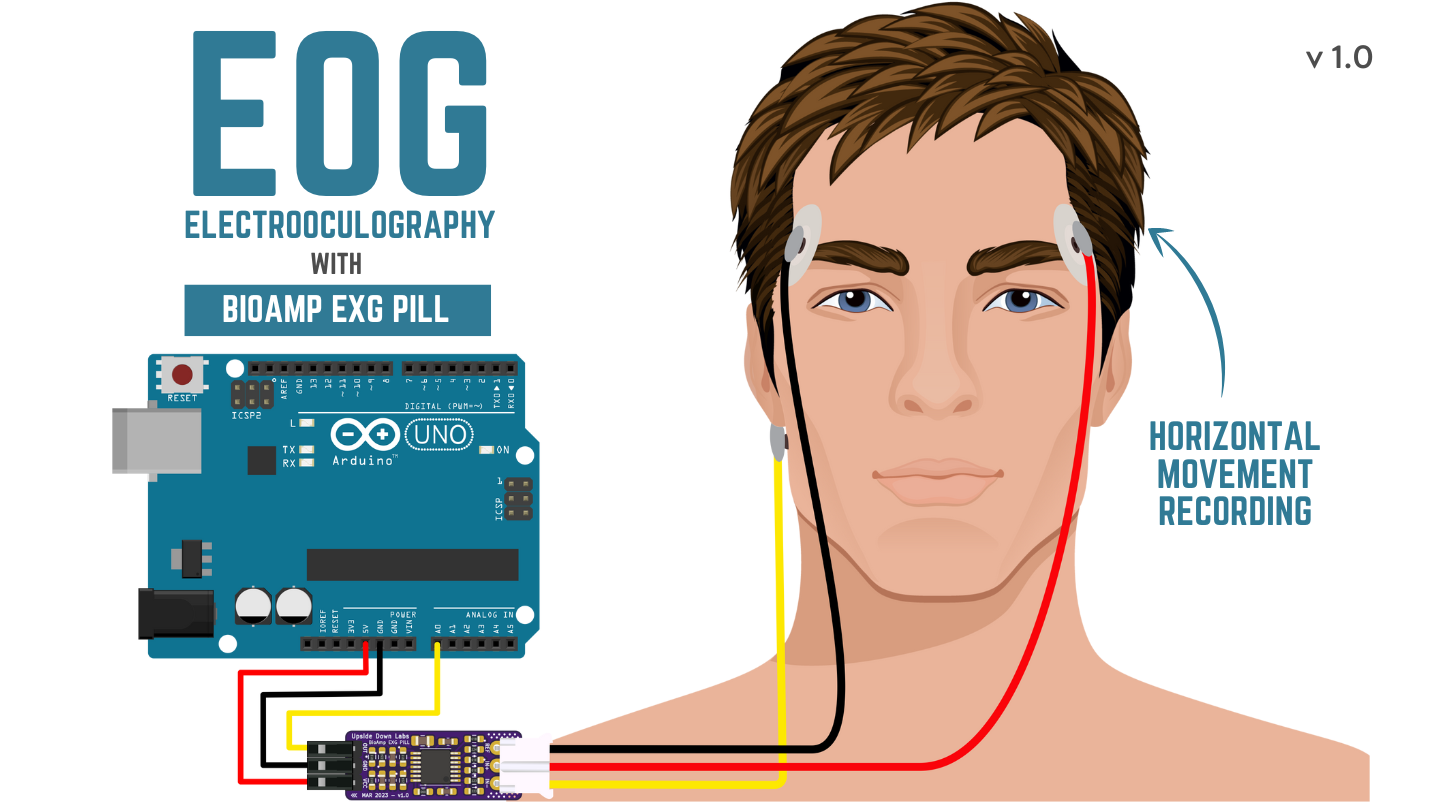
Horizontal EOG Placement#
Connect the BioAmp cable to gel electrodes.
Peel the plastic backing from electrodes.
Place the IN- cable on the right side of the eye, IN+ on the left side of the eye and REF (reference) at the bony part, on the back side of your earlobe as shown in the diagram above.
Vertical EOG recording:
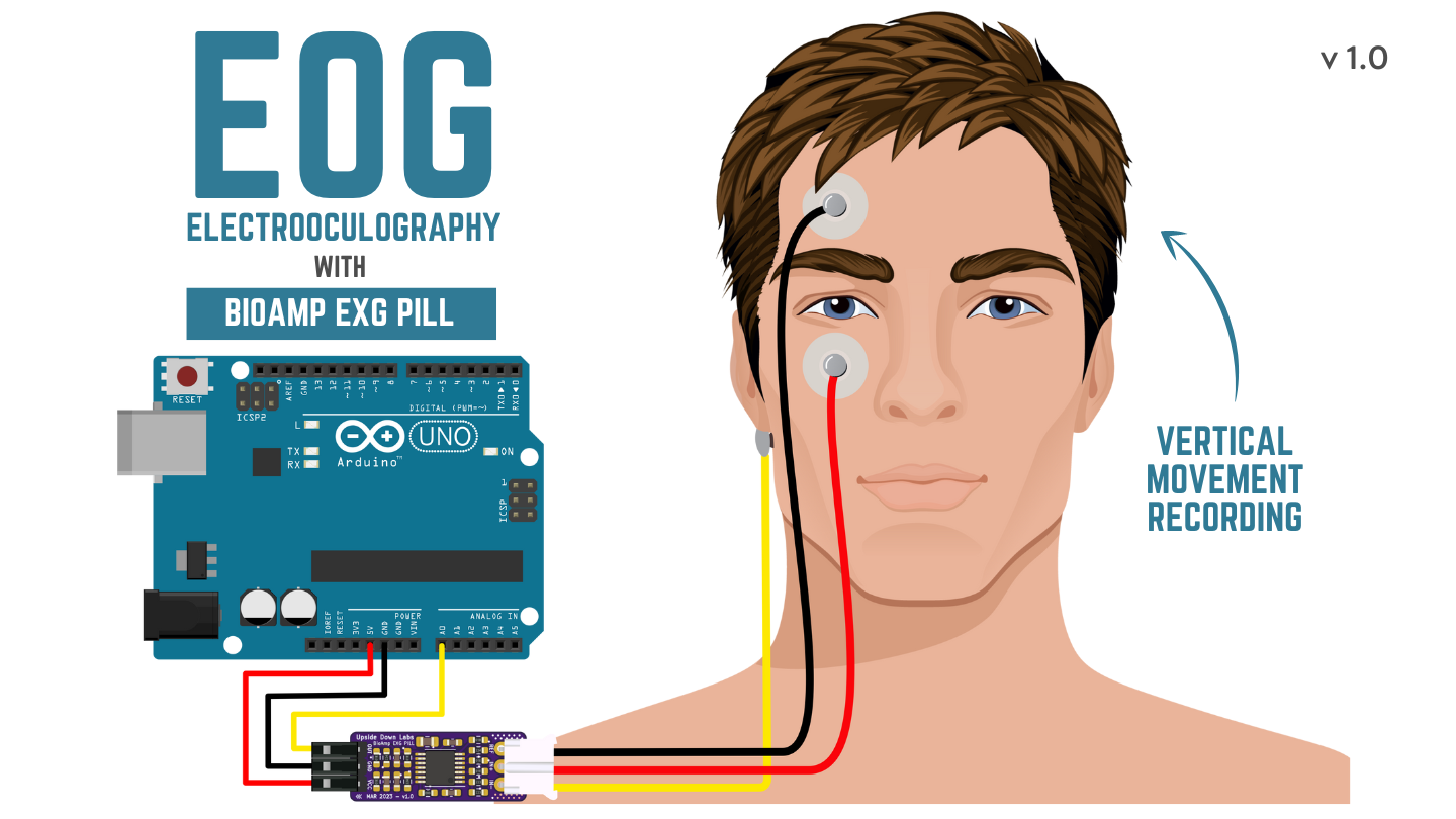
Vertical EOG Placement#
Connect the BioAmp cable to gel electrodes.
Peel the plastic backing from electrodes.
Place the IN- & IN+ cables above and below the eye respectively and REF (reference) at the bony part, on the back side of your earlobe as shown in the diagram above.
Uploading the code#
Connect the Arduino UNO Development Board to your laptop using the USB cable. To upload the code use Arduino IDE latest version (v2.3.8+).
Choose and copy one of the following Arduino sketches based on your requirements:
Go to
Toolsmenu, navigate toBoard, and select Arduino UNO Development Board (UNO R3/ R4/ Minima/ WiFi or any other board).In the same menu, select the
Portto which your Arduino Uno is connected.Tip: To find the correct COM Port, disconnect your board and reopen the menu. The entry that disappears should be the right COM port.
Uploadthe code.
Tip
Check our complete documentation on How to upload the code.
Warning
For the best signal acquisition, ensure your laptop is not connected to a charger and maintain a distance of at least 5m from any AC appliances, read more about Tips for better signal acquisition.
Visualizing the EOG signals#
Using Chords Web
For visualizing the EOG signals, use Chords Web for quick and hassle-free real-time bio-potential signals visualization right from your browser, without installing any software.
Visualizing EOG signals on Chords Web#
Move your eyes up-down or left-right to see your EOG signals in real time on your laptop.
Using Arduino legacy v1.8.19
To visualize the signal on Arduino v1.8.19 we will use inbuilt Serial Plotter:
Navigate to (
Tools>Board) and select your Development board or Arduino UNO Board (if not detected automatically).Open the Serial Plotter (
Tools>Serial PlotterorCtrl+Shift+L) to visualize the EMG signals.Once the Serial Plotter is open, ensure the baud rate is set to
115200.Now move your eyes up-down or left-right to see your EOG signals in real time on your laptop.
Visualizing EOG signals on Arduino IDE v1.8.x#
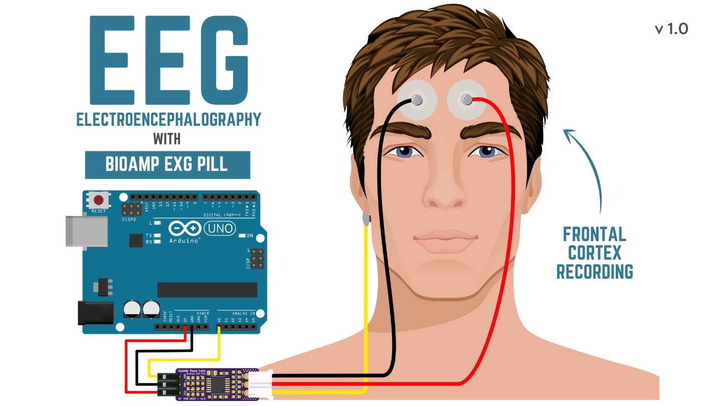
Step 8: Measuring Electroencephalography (EEG)#
Note
Electroencephalography (EEG) is an electrophysiological monitoring method to record electrical activity on the scalp. During the procedure, electrodes consisting of small metal discs with thin wires are pasted onto your scalp. The electrodes detect tiny electrical charges that result from the activity of your brain cells which are then amplified to appear on the computer screen. It is typically non-invasive, with the electrodes placed along the scalp.
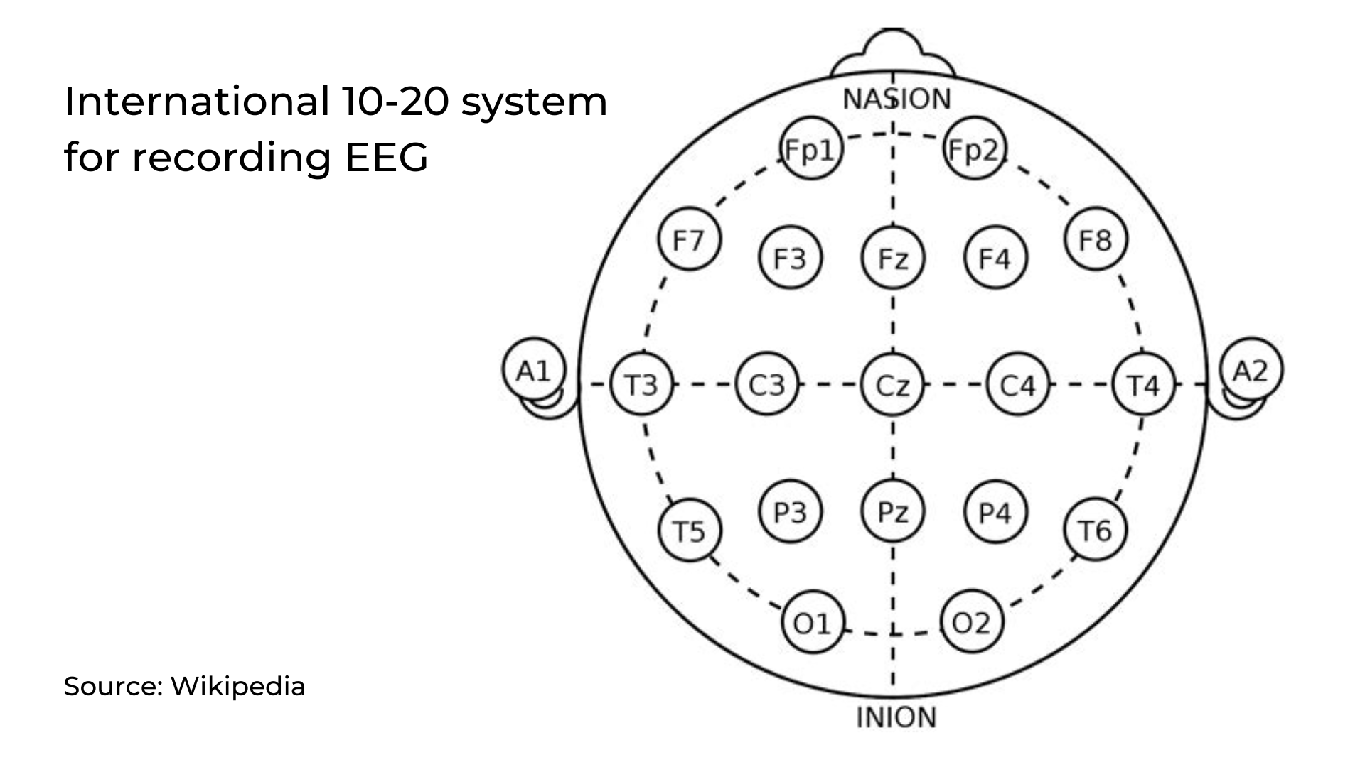
For recording EEG from different parts of the brain, you have to place the electrodes according to the International 10-20 system for recording EEG.
Electrodes placement#
We have 2 options to measure the EEG signals, either using the gel electrodes or using dry electrode based Brain BioAmp Band. You can try both of them one by one.
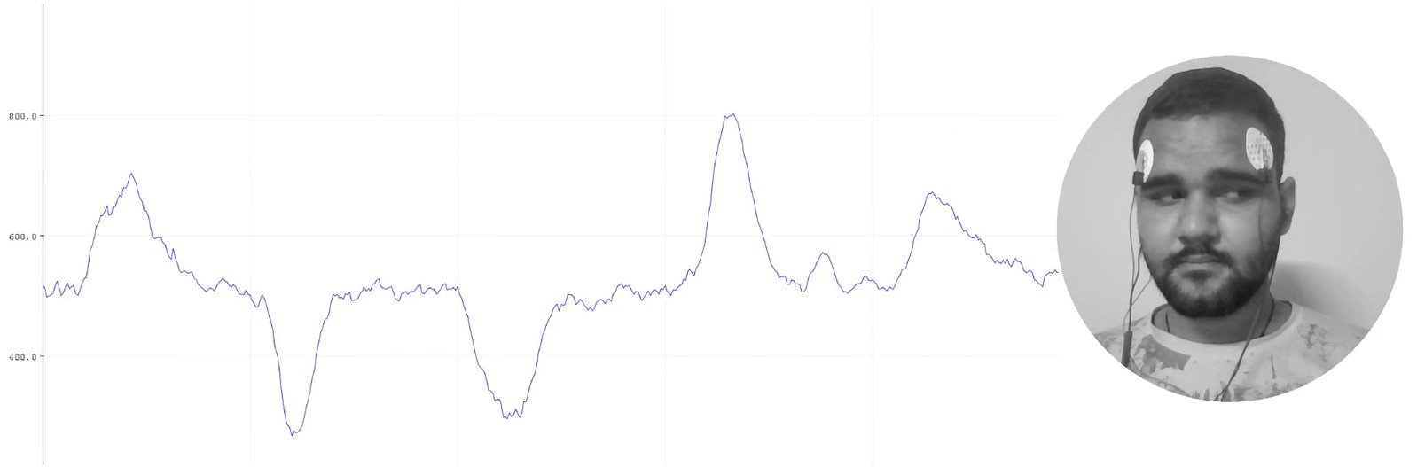
Using gel electrodes to record from prefrontal cortex part of brain:
EEG Placement#
Connect the BioAmp cable to gel electrodes.
Peel the plastic backing from electrodes.
Place the IN+ and IN- cables on Fp1 and Fp2 as per the International 10-20 system & REF (reference) at the bony part, on the back side of your earlobe as shown above.
Using Brain BioAmp Band to record from prefrontal cortex part of brain:
Connect the BioAmp cable to Brain BioAmp Band in a way such that IN+ and IN- are placed on Fp1 and Fp2 as per the International 10-20 system.
In this case, the REF (reference) should be connected using gel electrode. So connect the reference of BioAmp cable to the gel electrode, peel the plastic backing and place it at the bony part, on the back side of your earlobe.
Now put a small drop of electrode gel on the dry electrodes (IN+ and IN-) between the skin and metallic part of BioAmp cable to get the best results.
Tip
Visit the complete documentation on how to assemble and use the BioAmp Bands or follow the youtube video given below.
Tutorial on how to use the band:
Note
Similarly you can use the band to record EEG signals from the visual cortex part of brain by placing the dry electrodes on O1 and O2 instead of Fp1 and Fp2. Everything else will remain the same.
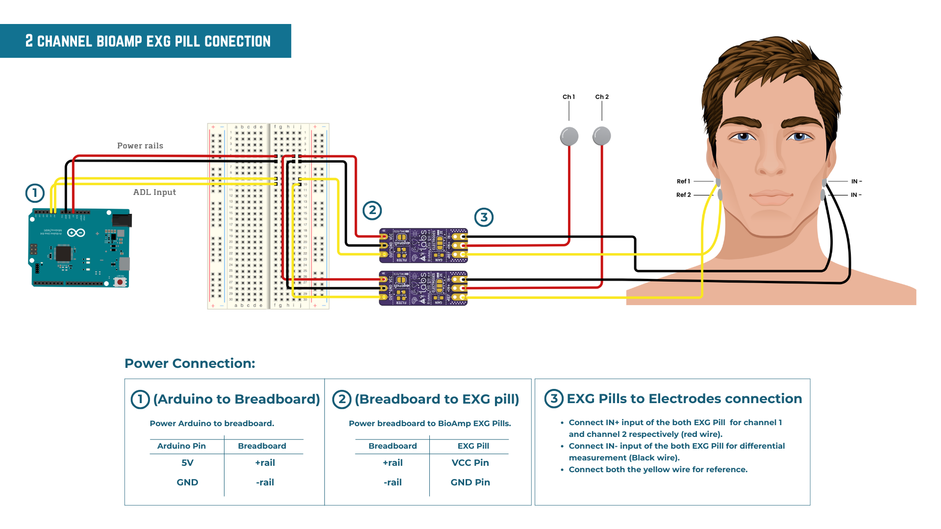
2-Channel EEG data#
To record 2-channel Electroencephalography (EEG) data using two BioAmp EXG Pills in conjunction with an Arduino Uno R4 Minima, following hardware setup is essential.
Required Components
2 x BioAmp EXG Pill
1 x Arduino Uno R4 Minima
1 x Breadboard
Jumper wires
Gel Electrodes
Hardware setup
To set up the hardware for 2-channel EEG recording, follow the connection steps below:
Powering the Modules: Connect the Arduino’s
5VandGNDpins to the power rails of the breadboard. SupplyVCCandGNDfrom the breadboard rails to both BioAmp EXG Pills.Signal Connections: Connect the
OUTpin of the first EXG Pill to the Arduino’s analog pinA0(Channel 1). Connect theOUTpin of the second EXG Pill to analog pinA1(Channel 2).- Electrode Placement:
Active Sites: Connect the
IN+(red wires) of each module to different EEG recording sites on the forehead (e.g., Fp1 and Fp2).Reference & Ground: Connect the
IN-(black wires) and bothREF(yellow wires) from both EXG Pills to a common reference electrode placed on a neutral location, such as the mastoid or earlobe.
This common reference configuration ensures clean and synchronized signal acquisition across both channels.
Uploading the code#
Connect the Arduino UNO Development Board to your laptop using the USB cable. To upload the code use Arduino IDE latest version (v2.3.8+).
Choose and copy one of the following Arduino sketches based on your requirements:
Go to
Toolsmenu, navigate toBoard, and select Arduino UNO Development Board (UNO R3/ R4/ Minima/ WiFi or any other board).In the same menu, select the
Portto which your Arduino Uno is connected.Tip: To find the correct COM Port, disconnect your board and reopen the menu. The entry that disappears should be the right COM port.
Uploadthe code.
Tip
Check our complete documentation on How to upload the code.
Warning
For the best signal acquisition, ensure your laptop is not connected to a charger and maintain a distance of at least 5m from any AC appliances, read more about Tips for better signal acquisition.
Visualizing the EEG signals#
Using Chords Web
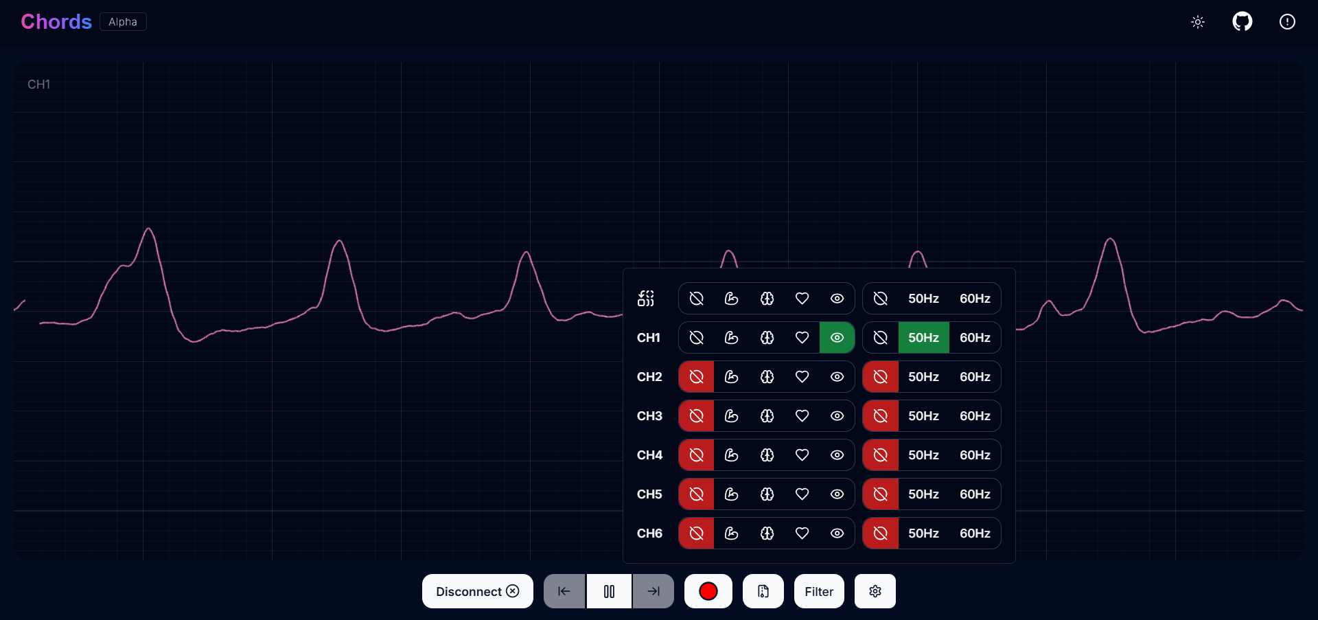
For visualizing the EEG signals, use Chords Web for quick and hassle-free real-time bio-potential signals visualization right from your browser, without installing any software.
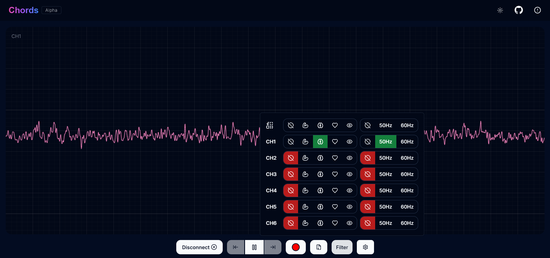
Visualizing EEG signals on Chords Web#
The signals that you can see on the screen right now are originating from prefrontal cortex part of your brain and propagating through all the layers to the surface of your skin.
You have placed the electrodes on the forehead (Fp1 & Fp2), the BioAmp EXG Pill is amplifying those signals so that we can detect it and finally sending it to the ADC (Analog to Digital Convertor) of your Arduino Uno and the signals are being visualized in Chords Web.
Tip
To ensure you’re recording a high-quality signal, refer to the detailed guide here: Troubleshooting EEG Signal Quality.
We hope everything is clear now and you understand how the signals are propagating from your brain to the screen of the laptop.
Glimpses of previous versions#
The BioAmp EXG Pill can be used in a variety of ways, the YouTube video below shows a potential way of using v0.7 of
BioAmp EXG Pill.
A lot has improved in terms of interference rejection and flexibility from v0.7 to v1.0 of the BioAmp EXG Pill. The YouTube video
below shows the ECG, EMG, EOG, and EEG recording using v1.0b of device.
Real-world Applications#
BioAmp EXG Pill is perfect for researchers, makers, and hobbyists looking for novel ways to sample biopotential data. It can be used for a wide variety of interesting biosensing projects, including:
AI-assisted detection of congestive heart failure using CNN (ECG)
Heart-rate variability calculation to detect heart ailments (ECG)
Prosthetic arm (servo) control (EMG)
Controlling a 3DOF robotic arm (EMG)
Real-time game controllers (EOG)
Blink detection (EOG)
Capturing photos with a blink of an eye (EOG) and many more examples.
Project ideas & tutorials#
Projects on Instructables
Below are some projects made by students using the BioAmp EXG Pill.
These are some of the project ideas but the possibilities are endless. So create your own Human Computer Interface (HCI) and Brain Computer Interface (BCI) projects and share them with us at contact@upsidedownlabs.tech.