Muscle BioAmp Biscute#
Overview#
Muscle BioAmp BisCute is the most affordable DIY ElectroMyography (EMG) sensor in the world that allows you to create a Human-Computer Interface (HCI) projects with ease. In the process of building your own BisCute, you learn what goes into making a functional biopotential amplifier that can be used for amplifying sub mV signals generated by muscles inside your body to a level a microcontroller unit (MCU) can understand.
Features & Specifications#
Minimum Input Voltage |
3.3-30 V |
Input Impedance |
10^11 ohm |
Fixed Gain |
x2420 |
Bandpass filter |
72 – 720 Hz |
Compatible Hardware |
Any development board with an ADC (Arduino UNO & Nano, Adafruit QtPy, STM32 Blue Pill, BeagleBone Black, Raspberry Pi Pico, to name just a few) or any standalone ADC of your choice |
BioPotentials |
EMG (Electromyography) |
No. of channels |
1 |
Electrodes |
3 (Positive, Negative, and Reference) |
Dimensions |
3.0 x 4.5 cm |
Open Source |
Hardware + Software |
Hardware#
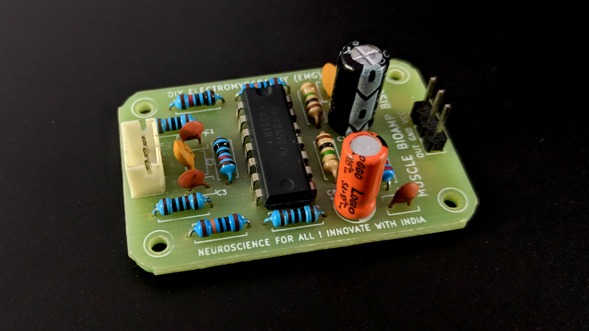
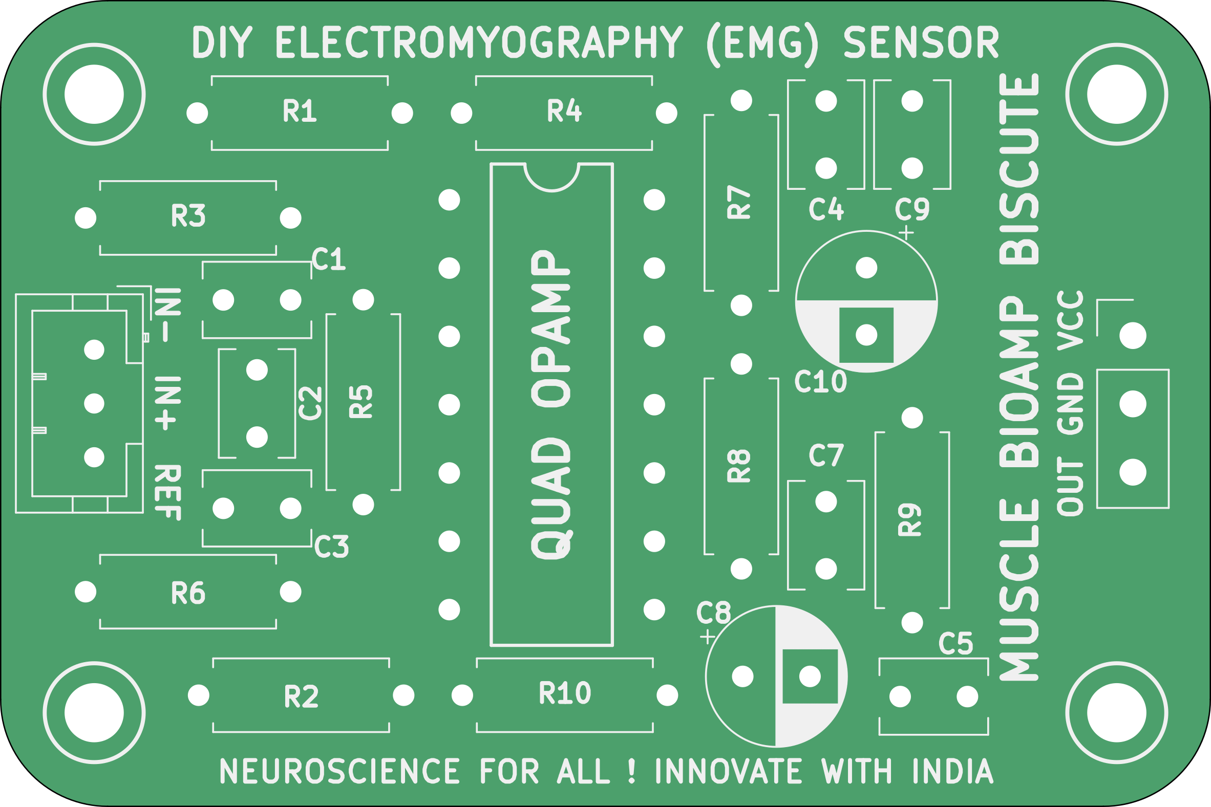
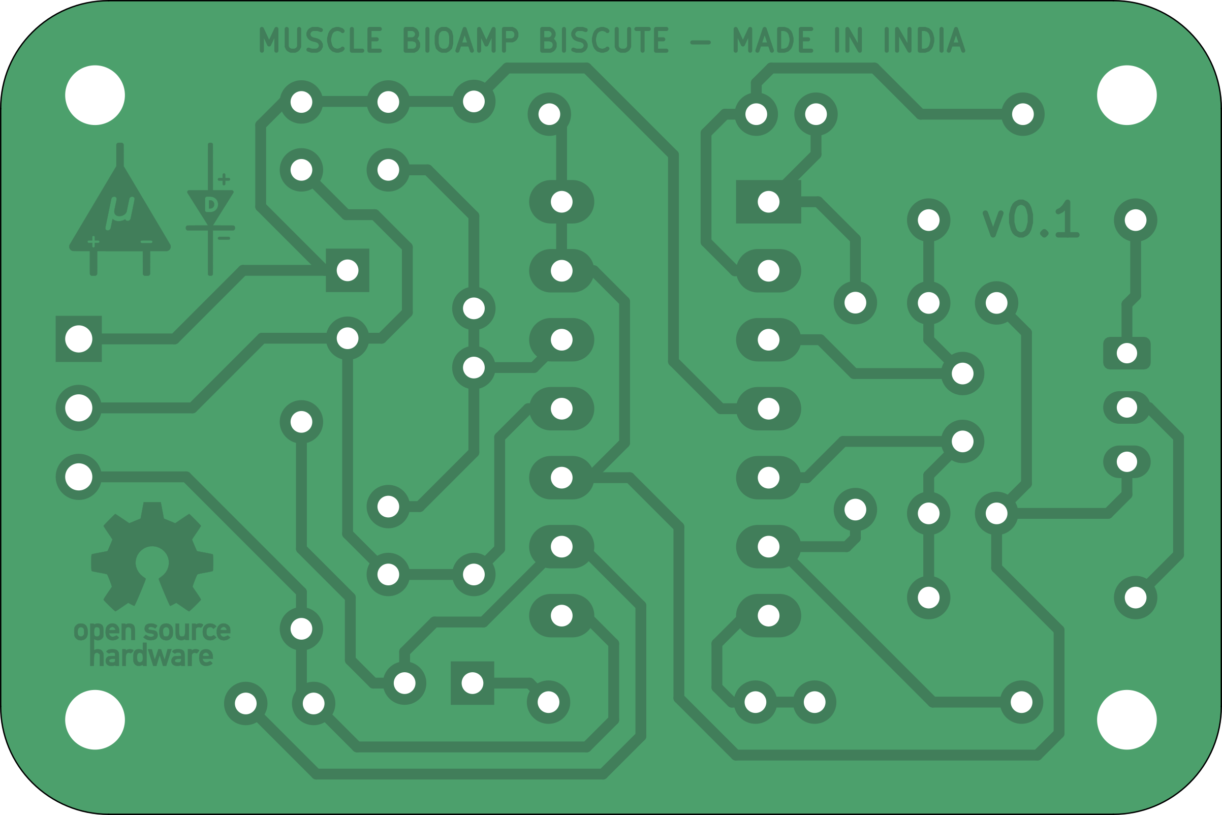
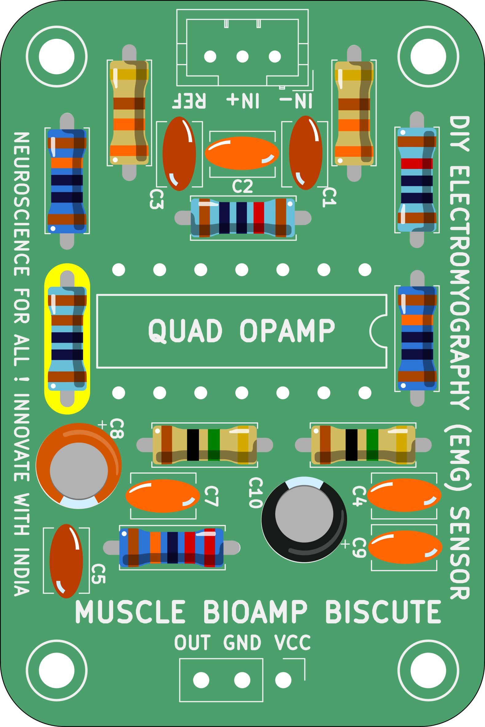
Images below shows a quick overview of the hardware design.
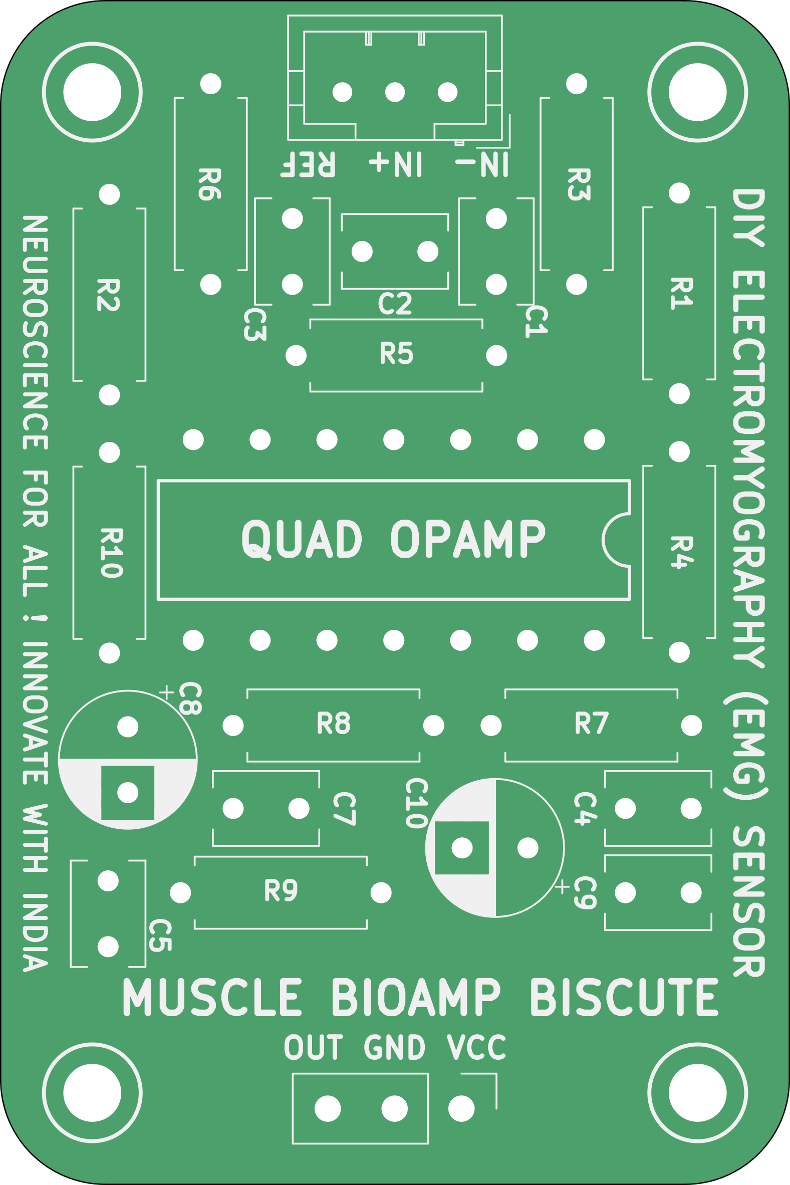
PCB Front
PCB Back
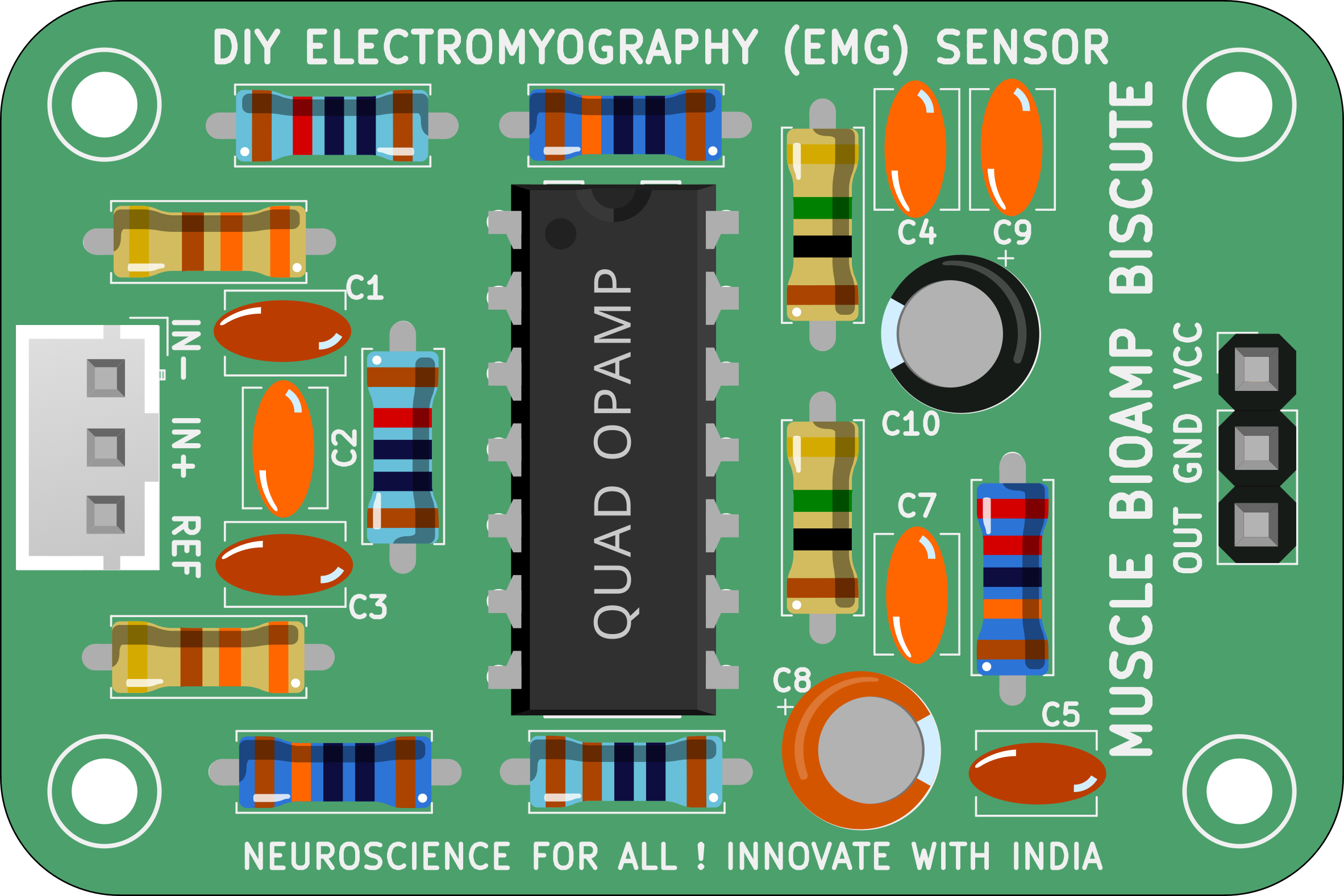
Assembled PCB#
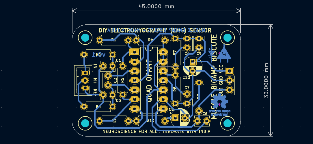
PCB Layout#
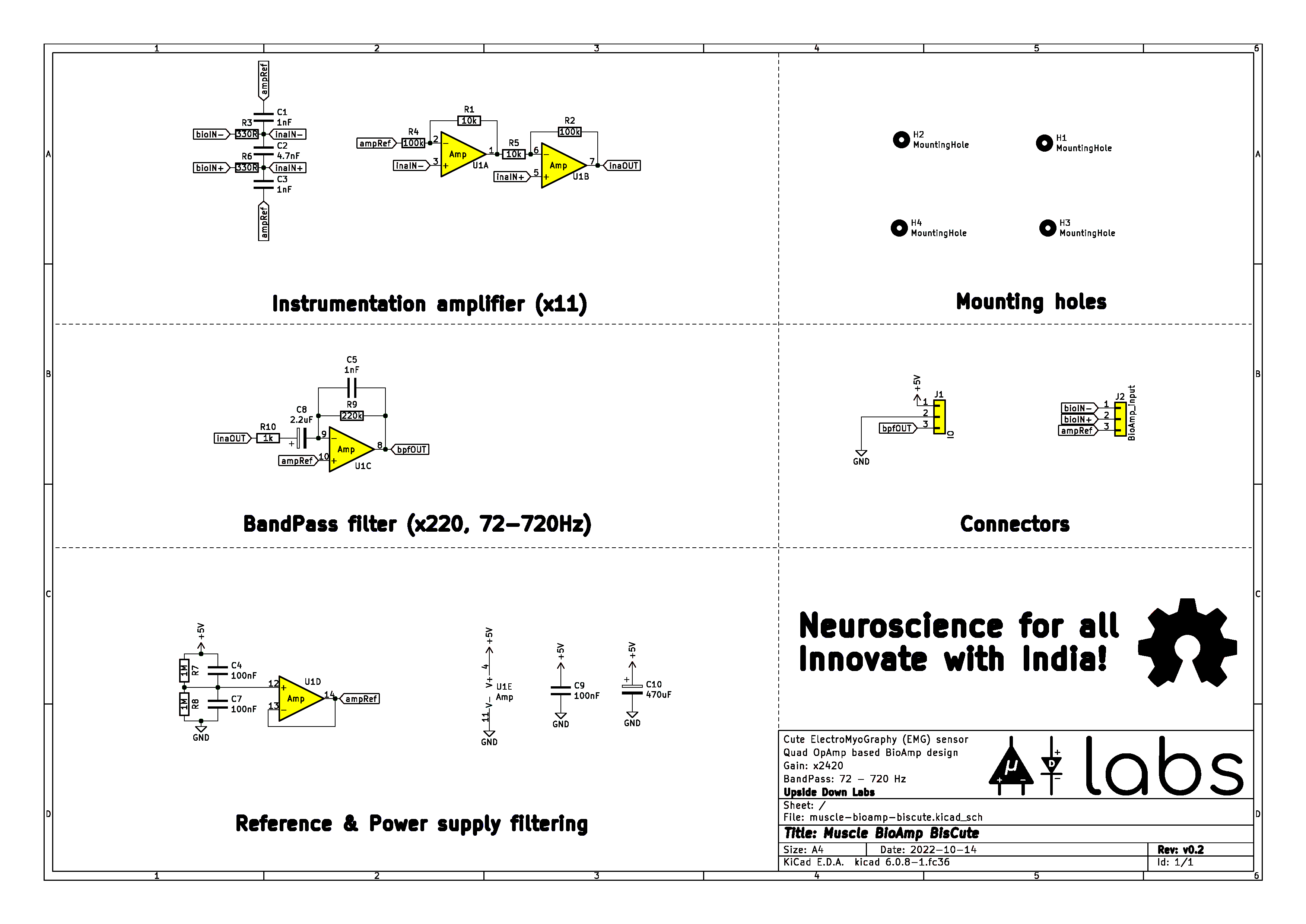
Schematic Diagram#
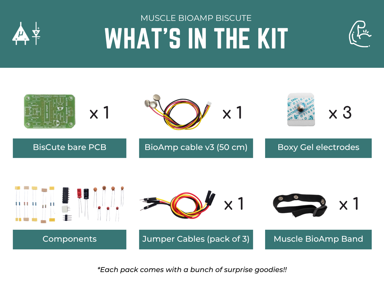
Contents of the kit#
Software requirements#
Before you start using the kit, please download Arduino IDE v1.8.19 (legacy IDE). Using this you’ll be able to upload the arduino sketches on your development board and visualise the data on your laptop.
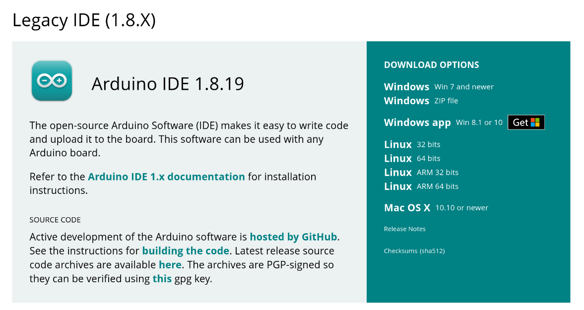
Arduino IDE v1.8.19 (legacy IDE)#
Visit Upside Down Labs Chords Web to visualize your bio-potential signals directly in the browser.
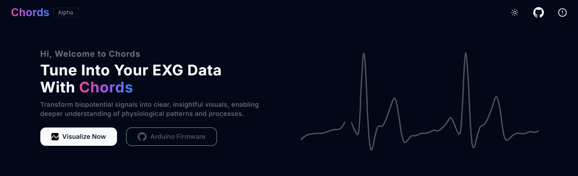
Chords Web Landing Page#
Getting started with Chords Web
Assembling the kit#
You can get Muscle BioAmp BisCute from our online stores (shipping worldwide) and for assembling the BisCute you can either take a look at this interactive BOM or the step by step guide given below.
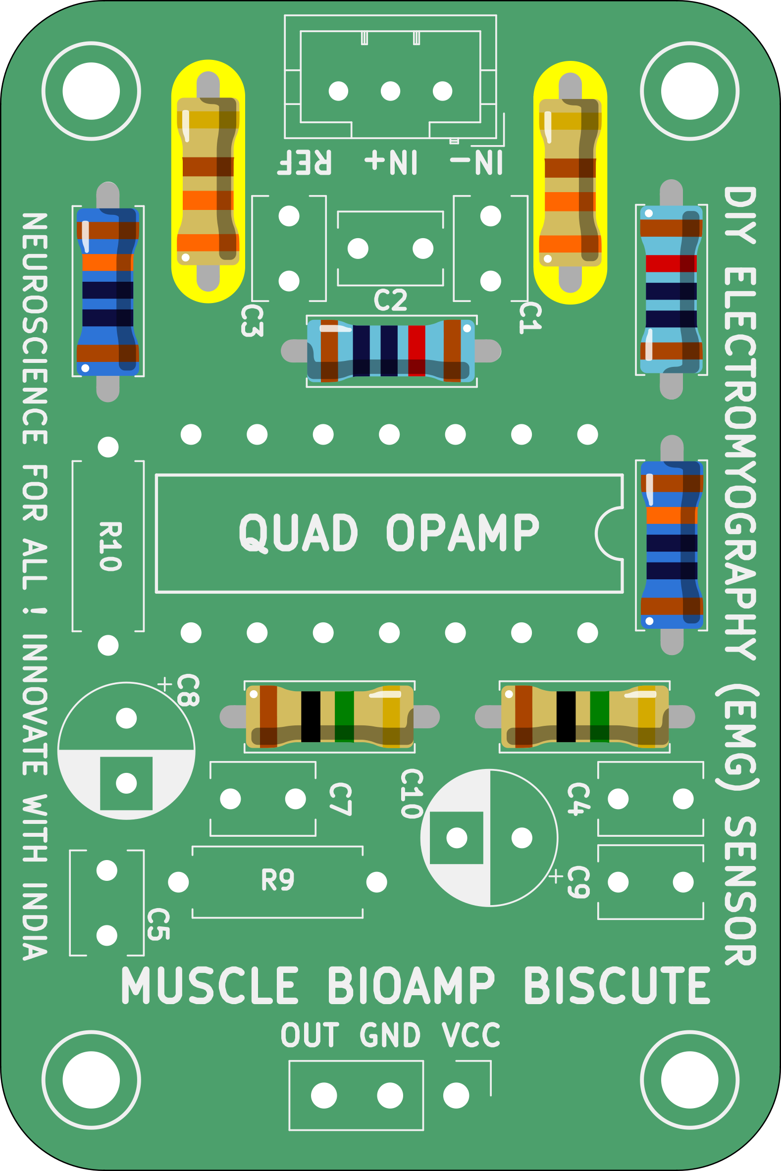
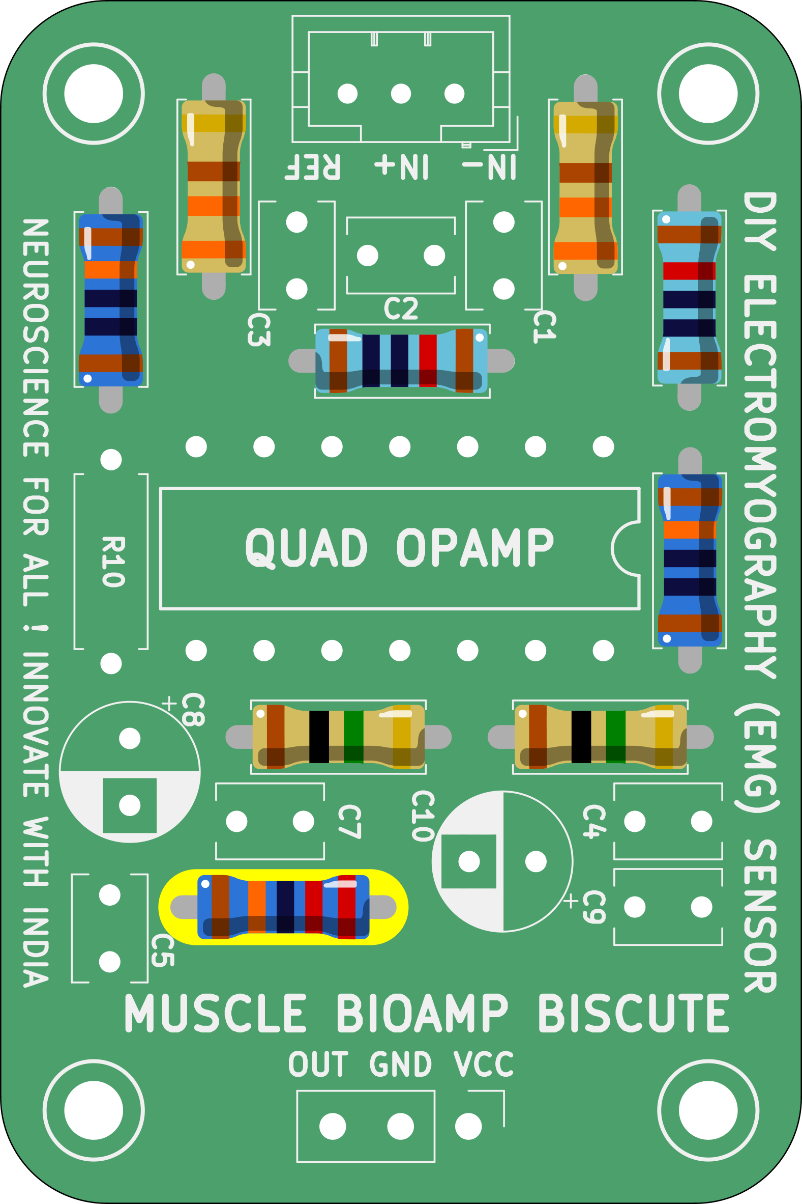
Note: Follow the highlighted yellow shapes to assemble your Muscle BioAmp BisCute!
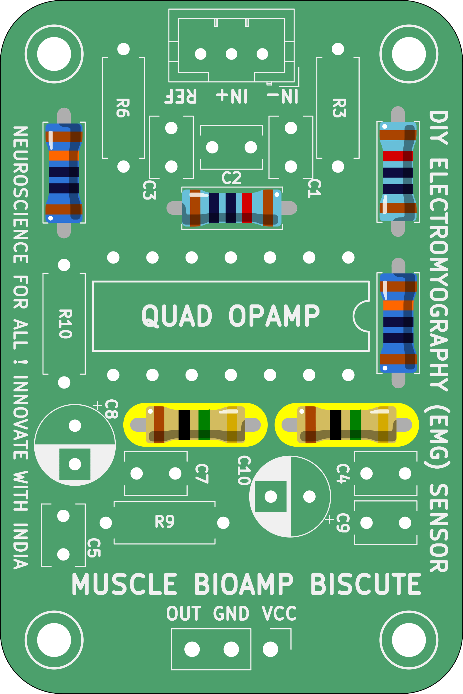
Step 1 - Bare Board#
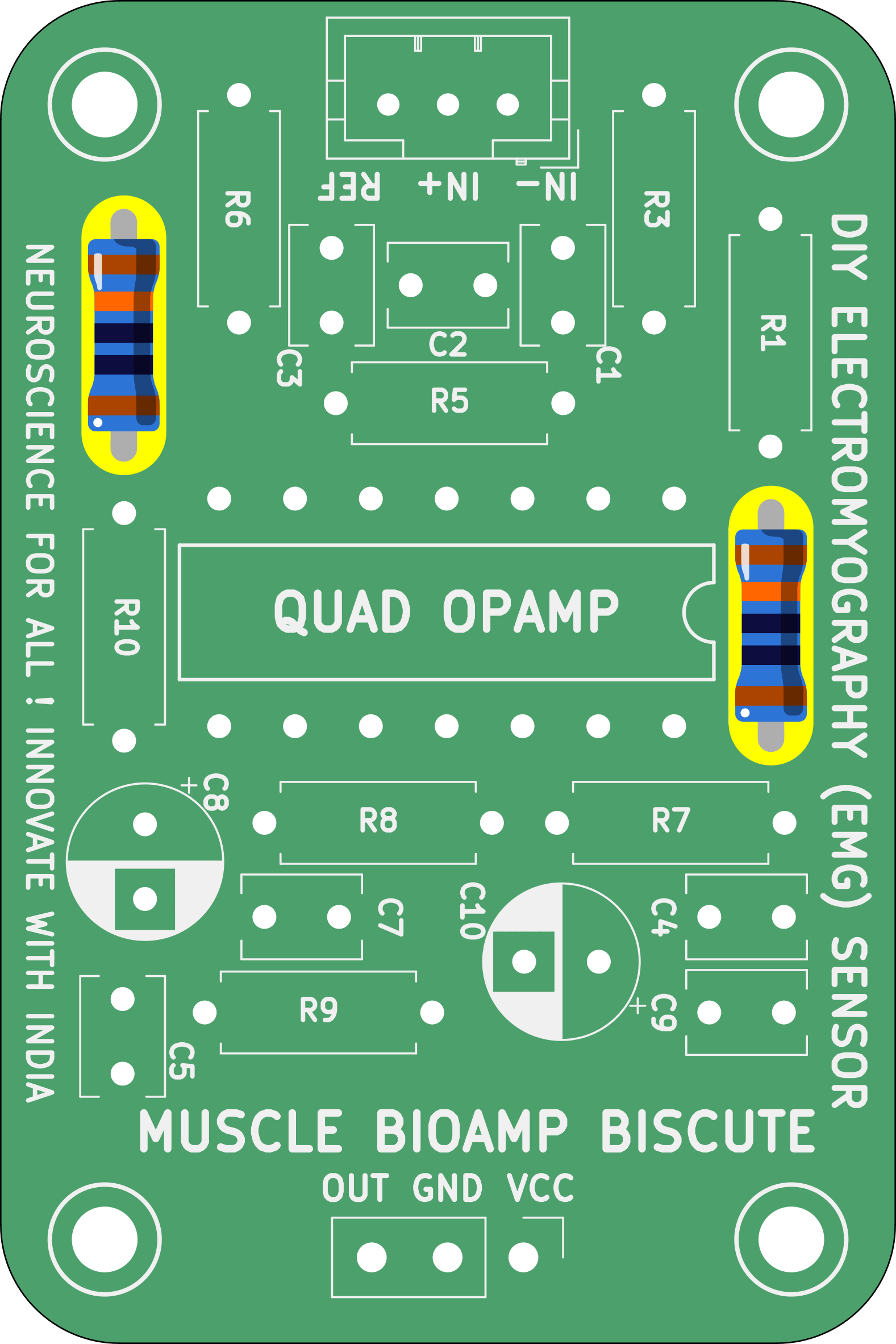
Step 2 - 100K Resistors#
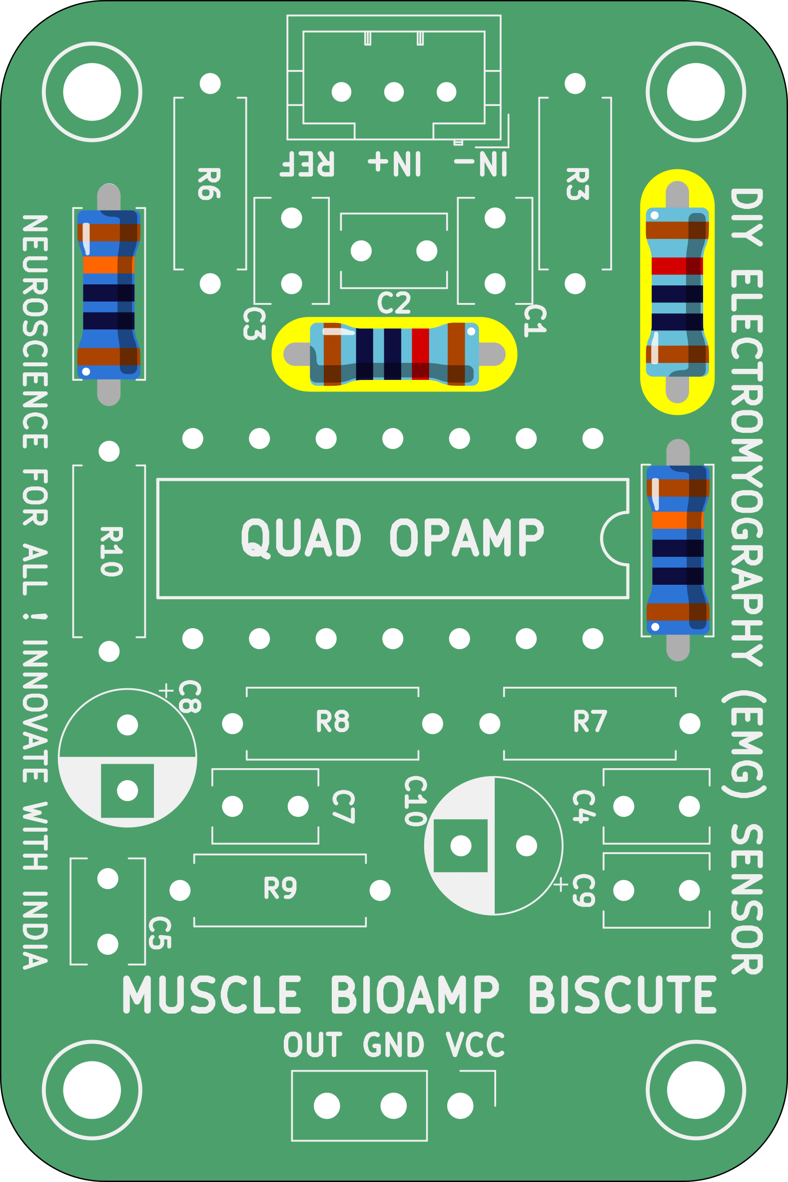
Step 3 - 10K Resistors#
Step 4 - 1M Resistors#
Step 5 - 330R Resistors#
Step 6 - 220K Resistor#
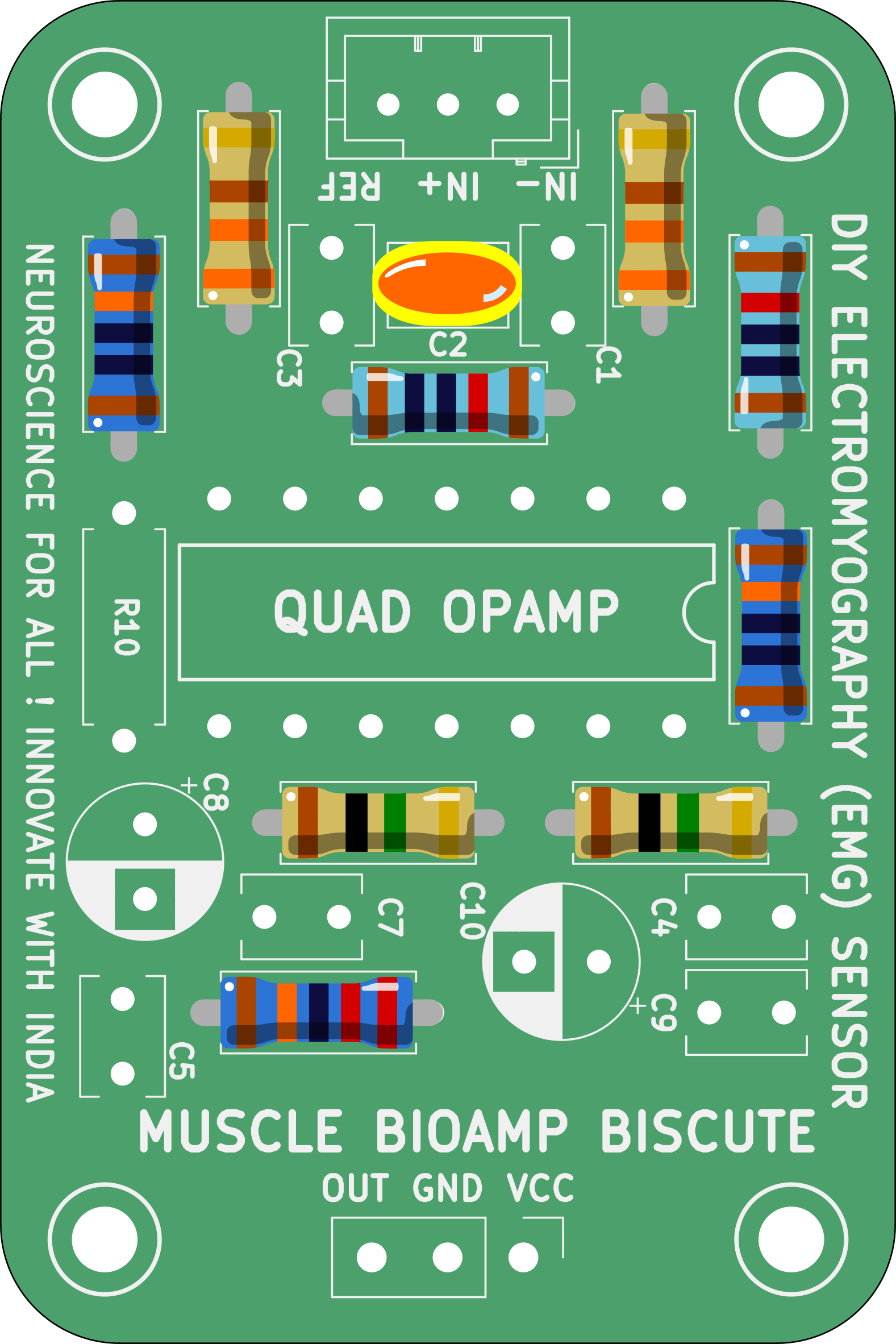
Step 7 - 4.7nF Capacitor#
Step 8 - 2.2uF Capacitor#
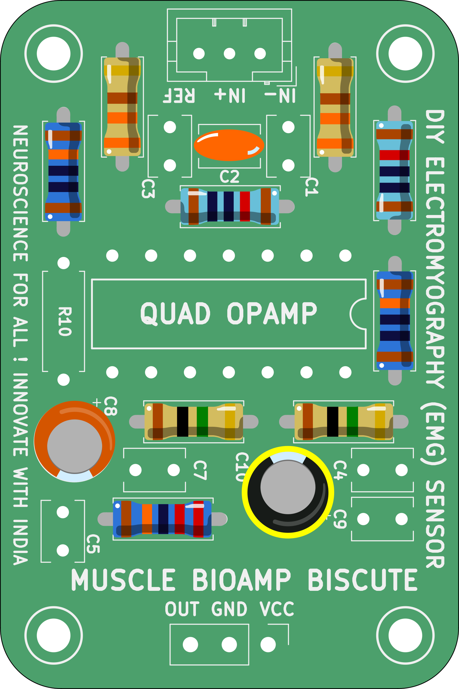
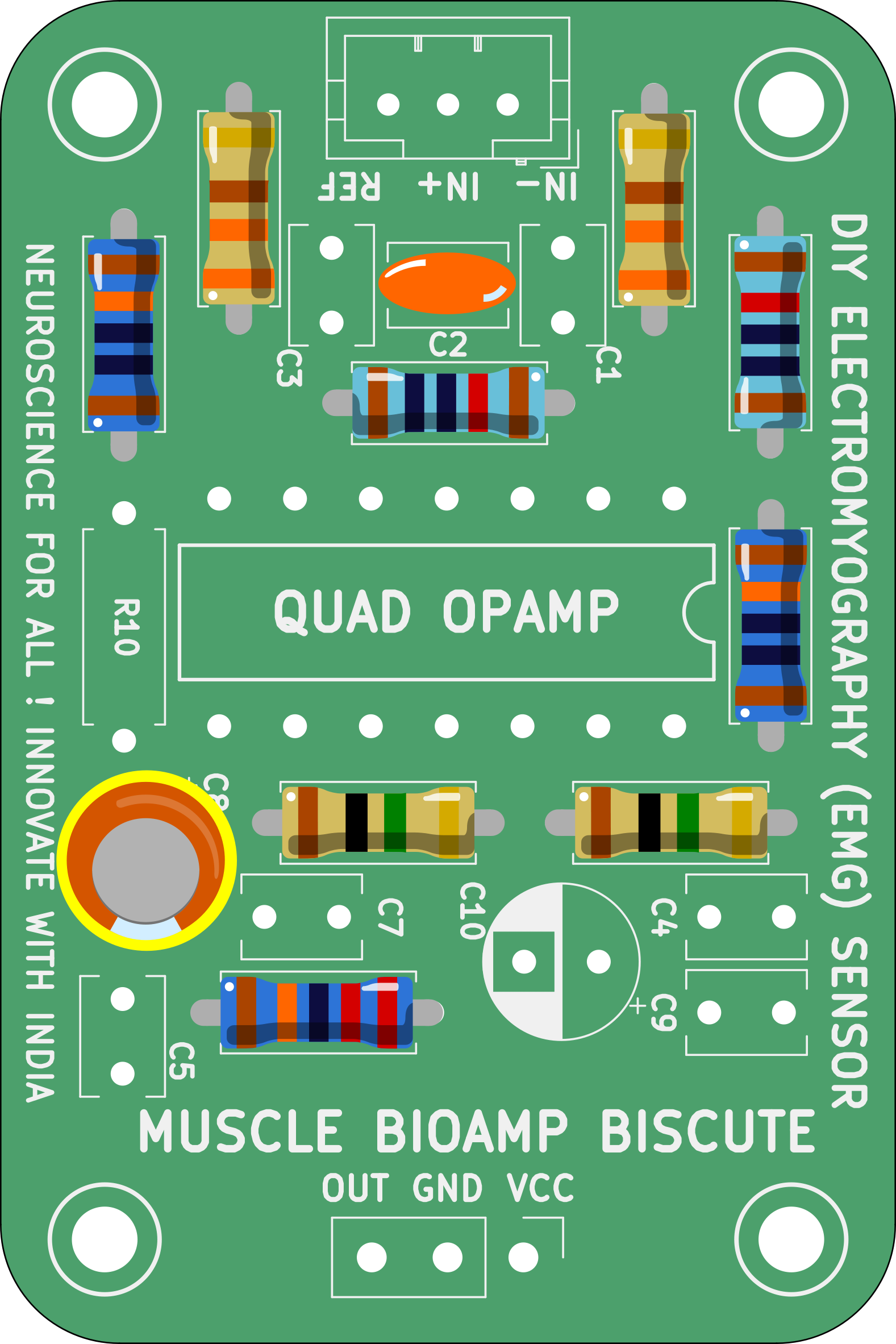
Step 9 - 470uF Capacitor#
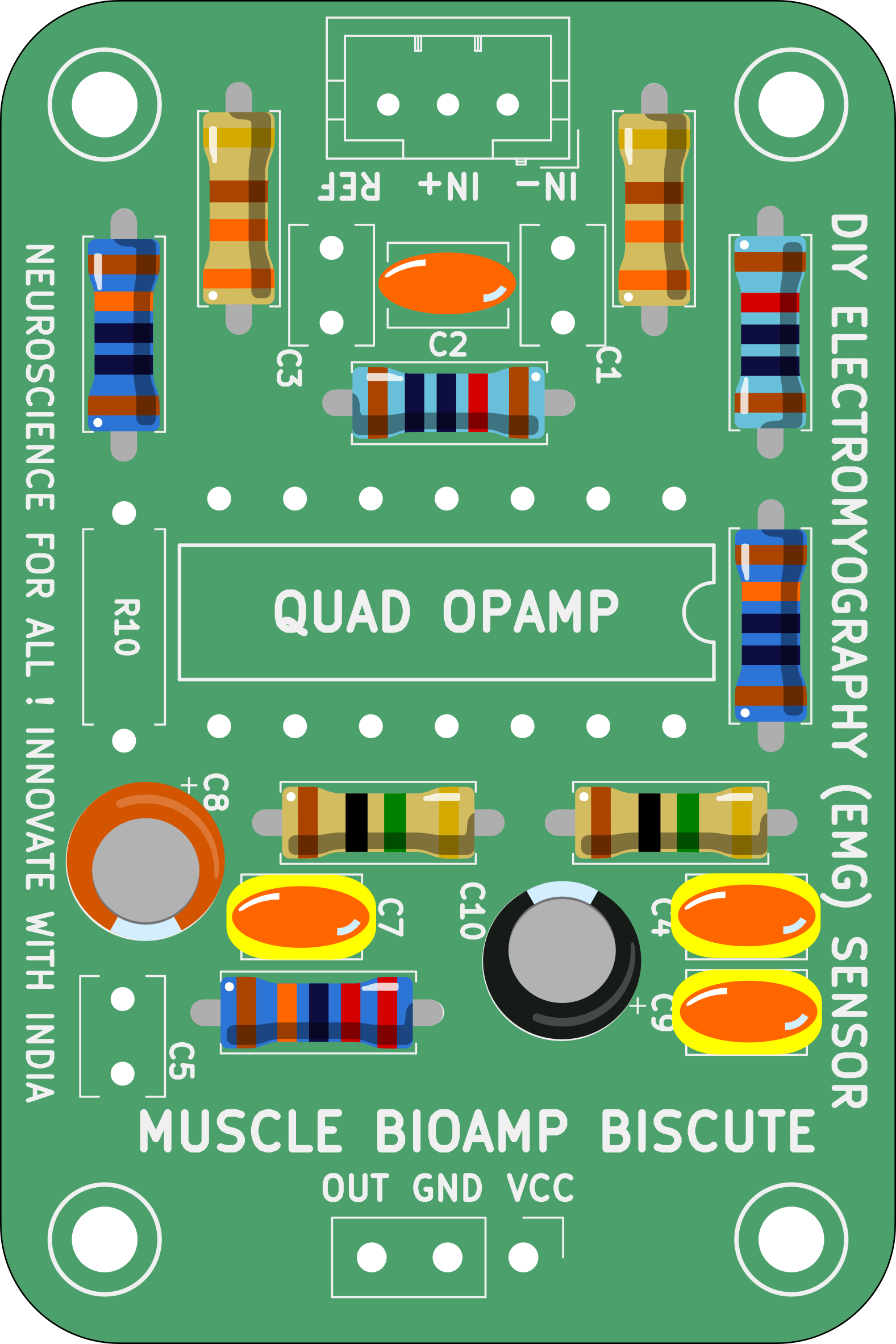
Step 10 - 100nF Capacitors#
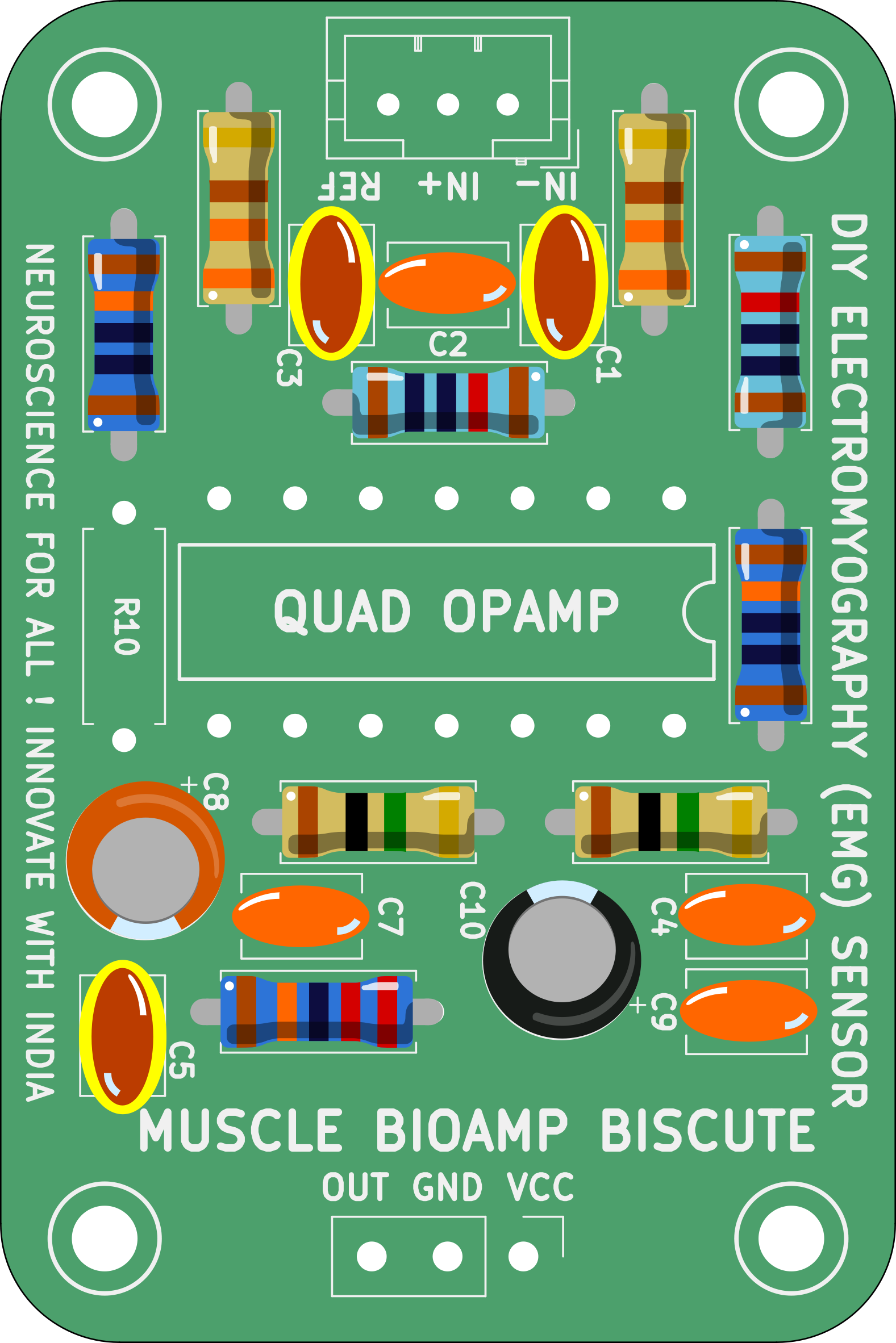
Step 11 - 1nF Capacitors#
Step 12 - 1K Resistor#
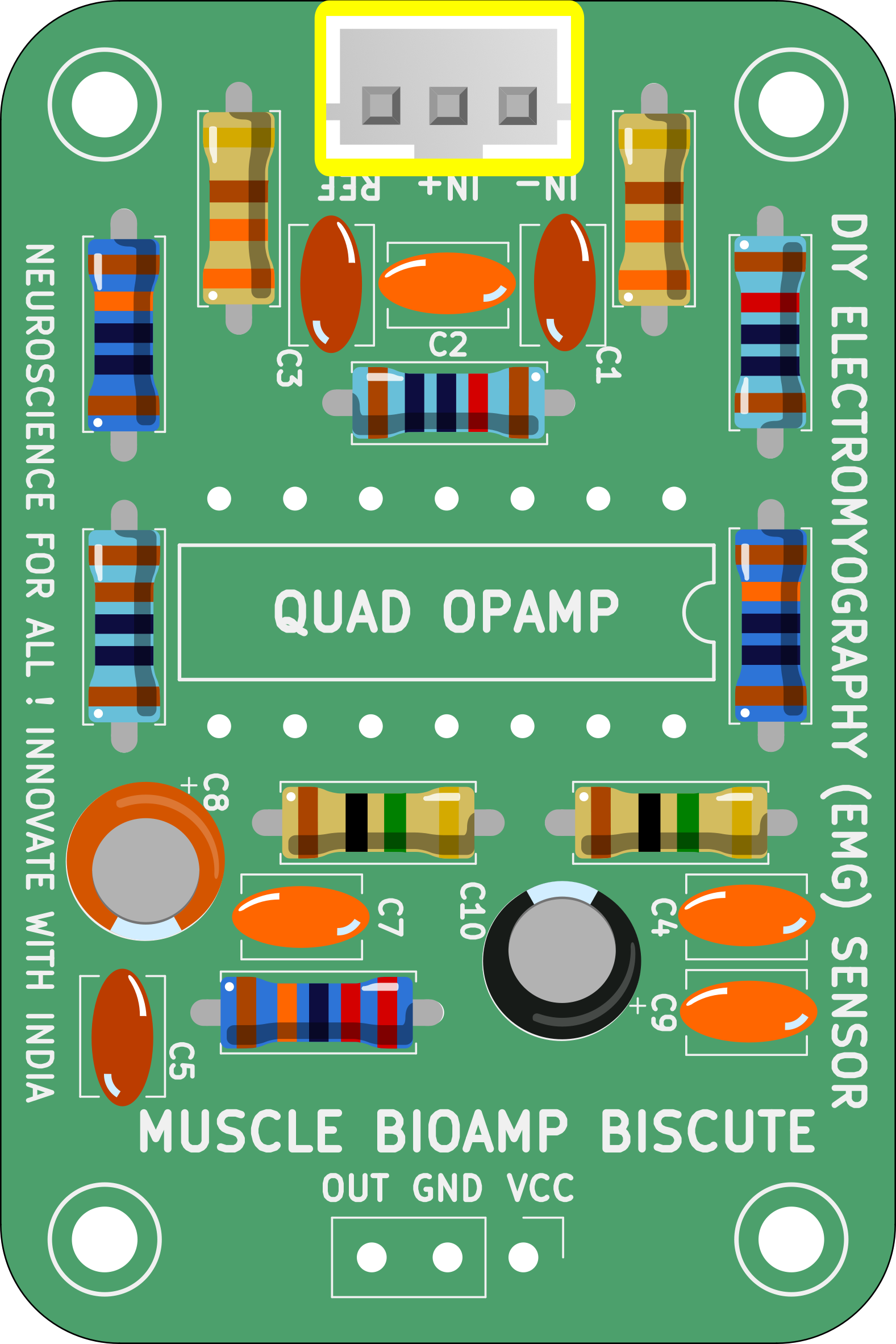
Step 13 - BioAmp Connector#
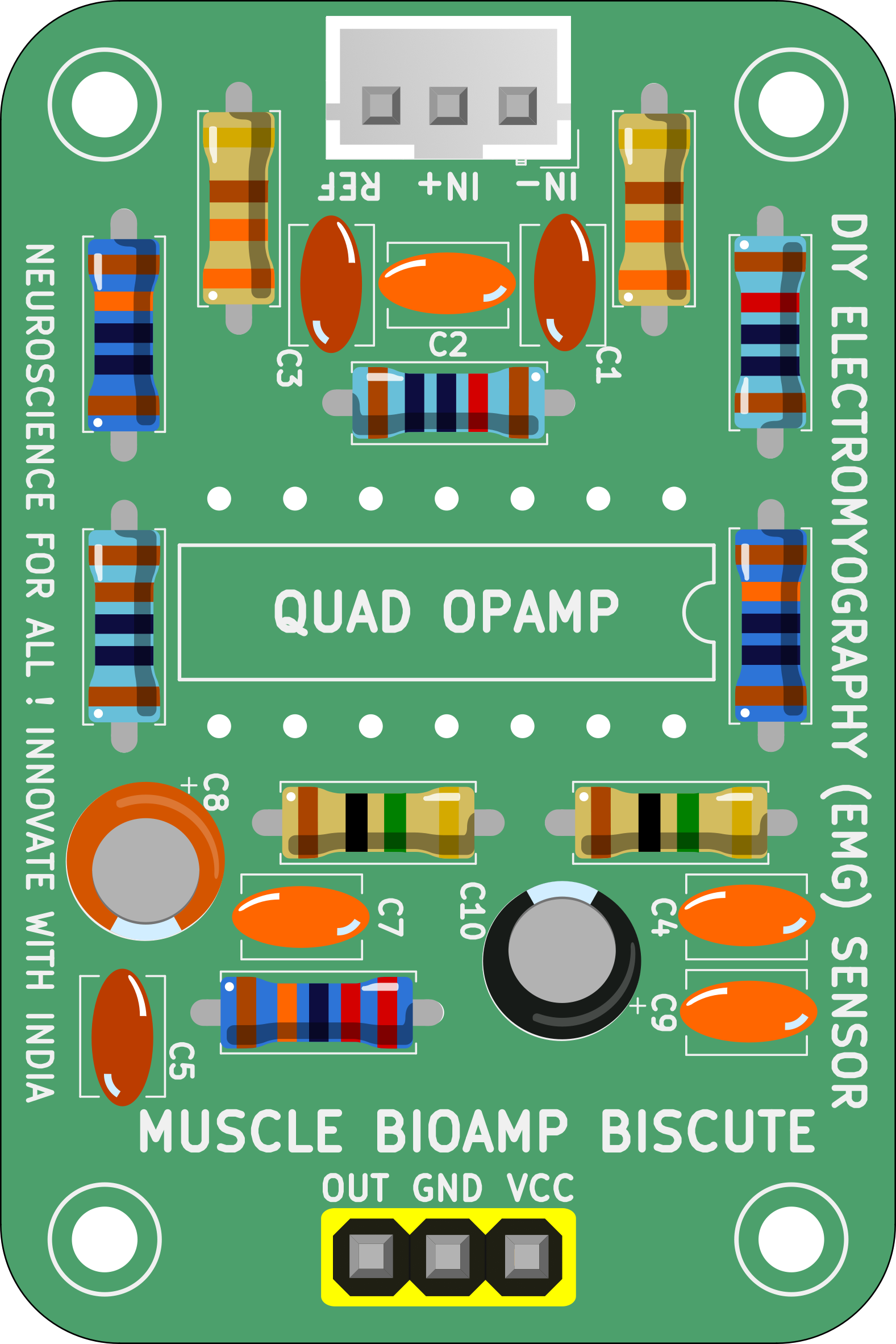
Step 14 - Header Pins#
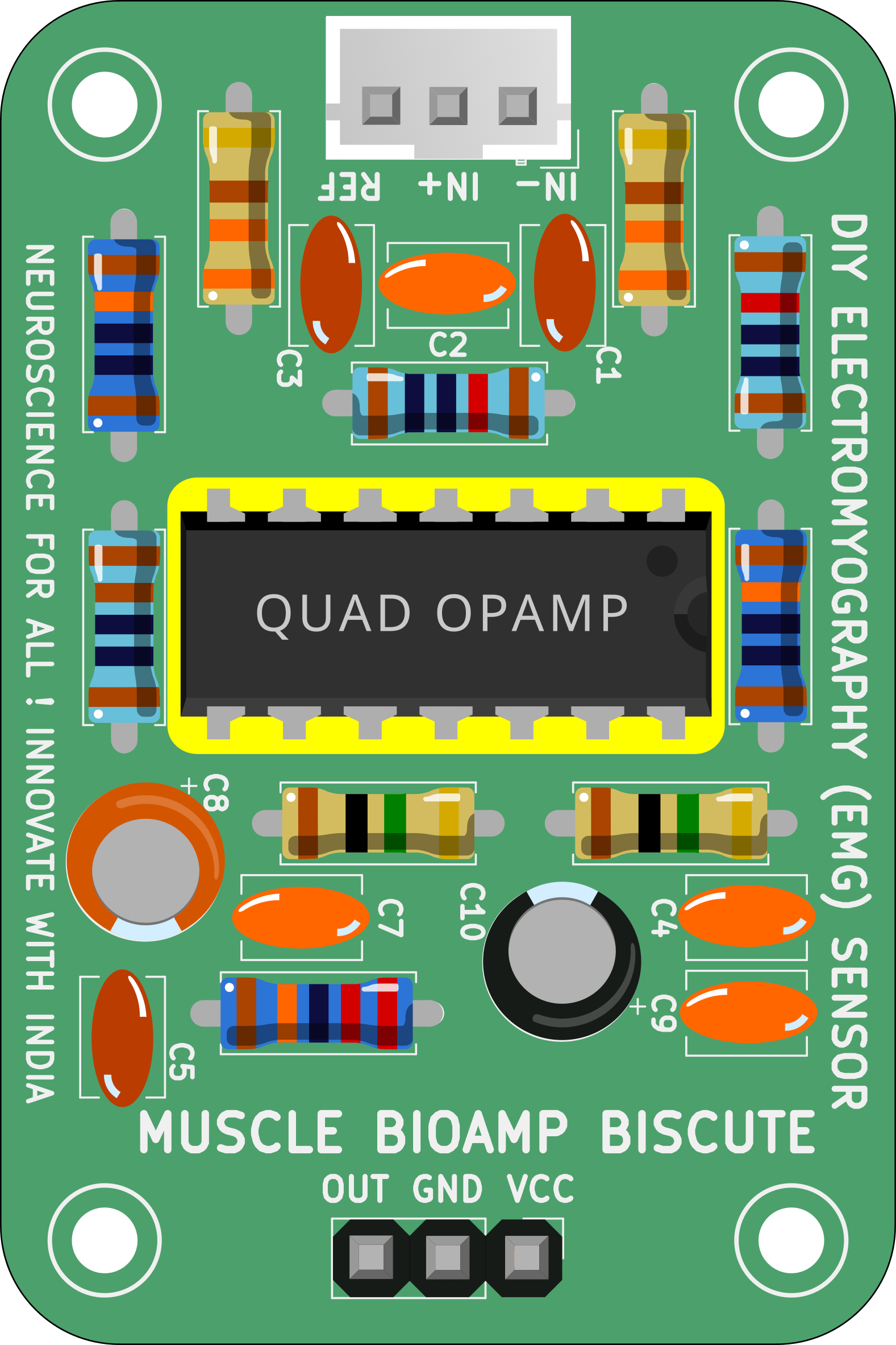
Step 15 - IC#
Still can’t figure out the assembly? You can watch the video below to assemble your Biscute.
Using the kit#
Step 1: Connect Arduino UNO R3#
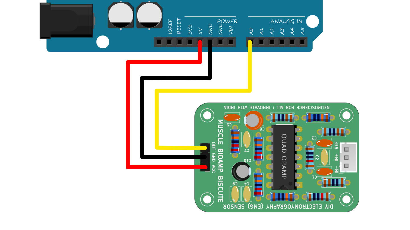
Connect VCC to either 5V or 3.3V, GND to GND, and OUT to Analog pin A0 of your Arduino UNO via jumper cables provided by us. If you are connecting OUT to any other analog pin, then you will have to change the INPUT PIN in the arduino sketch accordingly.
Note: For demonstration purposes we are showing connections of the sensor with Arduino UNO R3 but you can use any other development board or a standalone ADC of your choice.
Warning
Take precautions while connecting to power, if power pins (GND & VCC) are to be swapped, your sensor will be fried and it’ll become unusable (DIE).
Step 3: Connecting electrode cable#
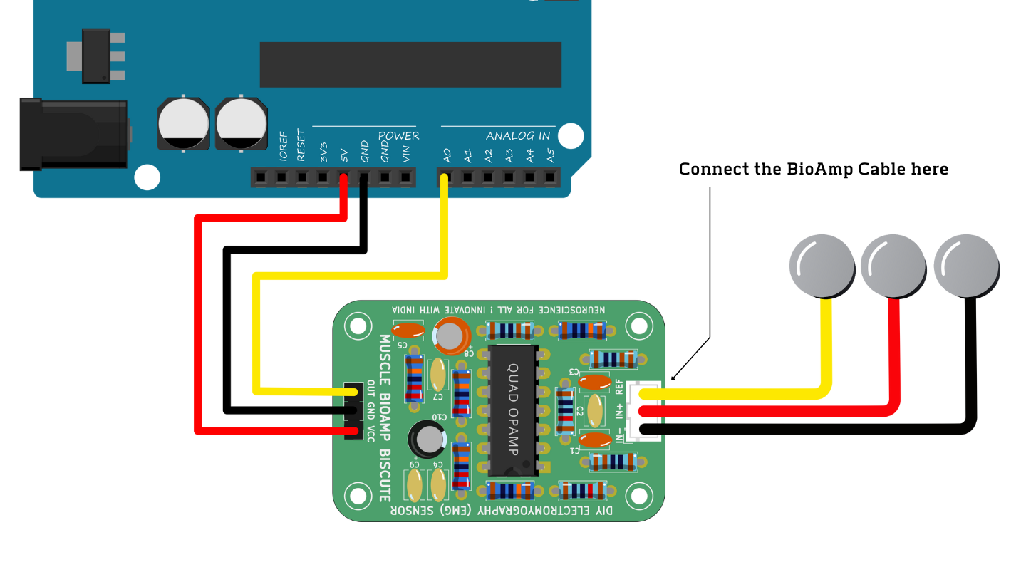
Connect the BioAmp cable to Muscle BioAmp Biscute by inserting the cable end in the JST PH connector as shown above.
Step 4: Skin Preparation#
Apply Nuprep Skin Preparation Gel on the skin surface where electrodes would be placed to remove dead skin cells and clean the skin from dirt. After rubbing the skin surface thoroughly, clean it with an alcohol wipe or a wet wipe.
For more information, please check out detailed step by step Skin Preparation Guide.
Step 5: Measuring EMG (ElectroMyoGraphy)#
Electrodes placement#
We have 2 options to measure the EMG signals, either using the gel electrodes or using dry electrode based Muscle BioAmp Band. You can try both of them one by one.
Using gel electrodes:
Connect the BioAmp cable to gel electrodes,
Peel the plastic backing from electrodes
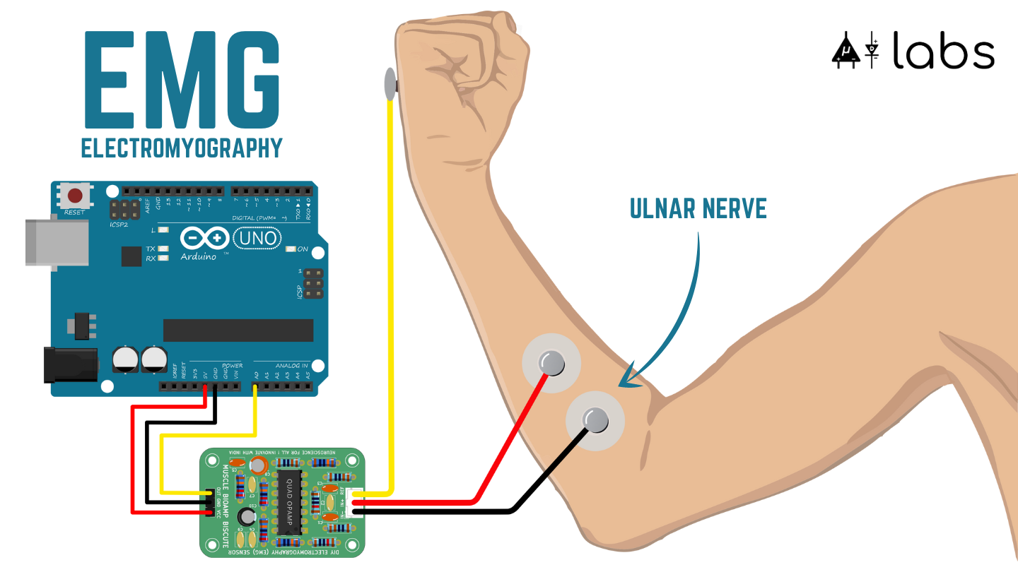
Place the IN+ and IN- cables on the arm near the ulnar nerve & REF (reference) at the back of your hand as shown in the connection diagram.
Using Muscle BioAmp Band:
Connect the BioAmp cable to Muscle BioAmp Band in a way such that IN+ and IN- are placed on the arm near the ulnar nerve & REF (reference) on the far side of the band.
Now put a small drop of electrode gel between the skin and metallic part of BioAmp cable to get the best results.
Tip
Visit the complete documentation on how to assemble and use the BioAmp Bands or follow the youtube video given below.
Tutorial on how to use the band:
Note
In this demonstration we are recording EMG signals from the ulnar nerve, but you can record EMG from other areas as well (biceps, triceps, legs, jaw etc) as per your project requirements. Just make sure to place the IN+, IN- electrodes on the targeted muscle and REF on a bony part.
Uploading the code#
Connect your Arduino UNO to your laptop using the USB cable (Type A to Type B). Copy paste any one of the arduino sketches given below in Arduino IDE v1.8.19 that you downloaded earlier:
Go to tools from the menu bar, select board option then select Arduino UNO. In the same menu,
select the COM port on which your Arduino Uno is connected. To find out the right COM port,
disconnect your board and reopen the menu. The entry that disappears should be the
right COM port. Now upload the code, & open the serial plotter from the tools menu to visualize
the EMG signals.
After opening the serial plotter make sure to select the baud rate to 115200.
Warning
Make sure your laptop is not connected to a charger and sit 5m away from any AC appliances for best signal acquisition.
Visualizing the EMG signals#
For visualizing the EMG signals, use Chords Web for quick and hassle-free real-time bio-potential signals visualization right from your browser, without installing any software.
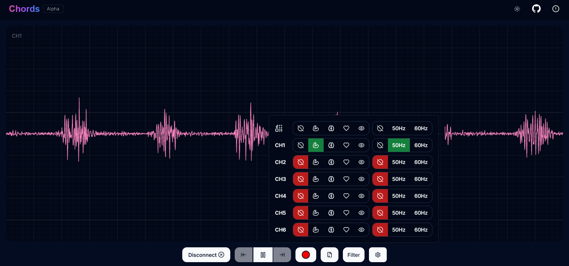
Visualizing EMG signals on Chords Web#
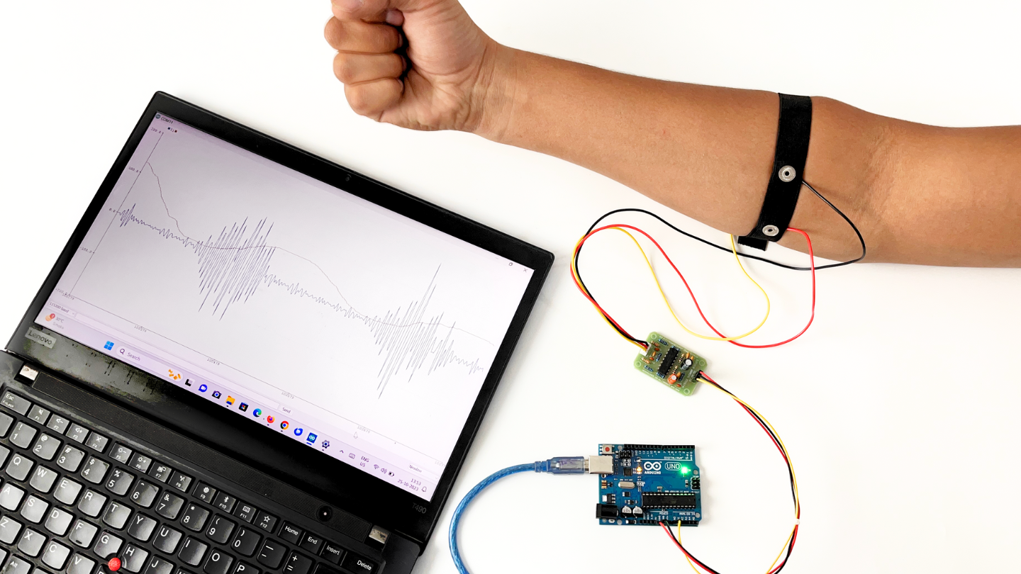
Now flex your arm to visualize the muscle signals in real time on your laptop.
Visualizing EMG signals on Arduino IDE v1.8.x#
Video tutorial: