NPG Lite - Beast Pack#
The Beast Pack is the most powerful kit in the lineup, designed for advanced users and researchers. With the VibZ+ Playmate, it enables full 6-channel bio-potential signal acquisition along with haptic and auditory feedback. Pre-assembled in a sturdy 3D-printed case, this kit provides maximum capability for neuroscience experiments, HCI/BCI applications, and biopotential signal research.
👉🏻 Get yours on CrowdSupply: Neuro PlayGround Lite
Neuro PlayGround Lite Beast Pack#
Contents of the kit#
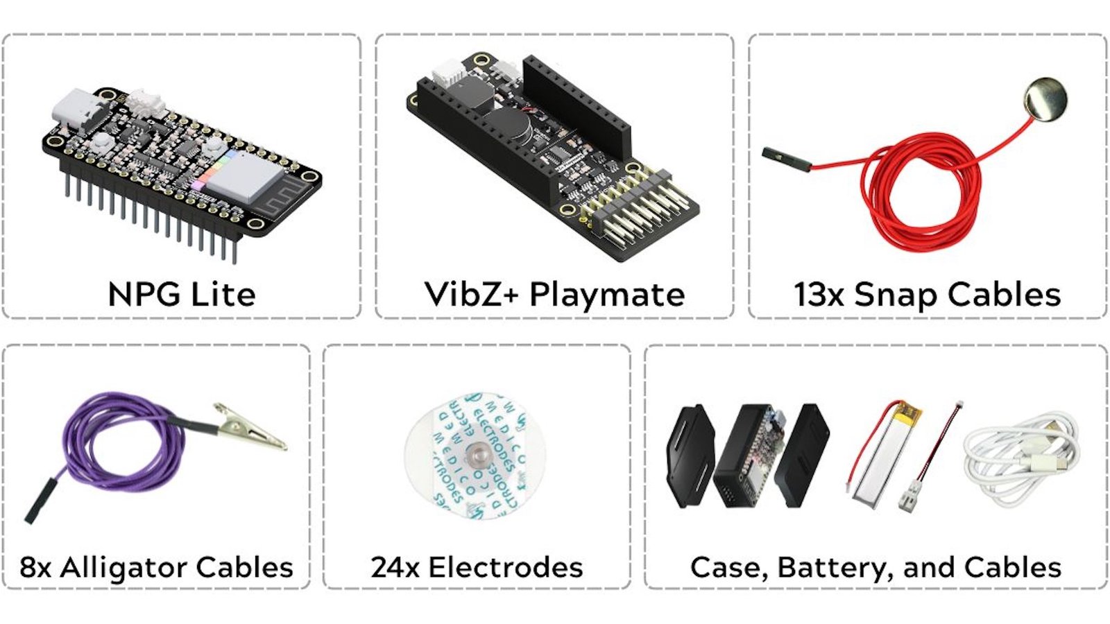
Kit Contents of NPG Lite Beast Pack#
Kit Contents |
Qty |
|---|---|
NPG Lite Board |
1 |
VibZ+ Playmate |
1 |
Snap Cables |
13 |
Alligator Cables |
8 |
Gel Electrodes |
24 |
LiPo Battery |
1 |
Type-C Cable |
1 |
3D-Printed Case |
1 |
VibZ+ Playmate#
VibZ+ Playmate builds on the VibZ by including an additional 3-channel BioAmp, making it possible to record and visualize up to 6 Bio-potential signal channels simultaneously. It retains the vibration motor for haptic feedback, buzzer for auditory cues, ON/OFF slide switch, QWIIC port, and electrode connector interface. This makes VibZ+ ideal for experiments where higher-resolution input or greater spatial coverage is essential, such as multi-channel EEG, EMG, or complex biofeedback applications.
Using the Kit#
This kit is designed for advanced bio-potential signal research, enabling users to quickly start recording and visualizing multi-channel data for high-resolution HCI/BCI experiments. The VibZ+ Playmate significantly enhances acquisition by including an additional 3-channel BioAmp, allowing simultaneous recording of up to six bio-potential signal channels. It retains the vibration motor, buzzer, and QWIIC port, making it ideal for multi-channel EEG, EMG, or complex biofeedback applications.
Step 1: Skin Preparation#
Apply Nuprep skin preparation Gel on the target areas where the Electrodes will be placed → Rub in circular motion → Clean with an alcohol swab or wet wipe.
For more information, please check out detailed step by step Skin Preparation Guide.
Step 2: Connect BioAmp Cables#
Using VibZ+, you can record up to 6-channel biopotential signals, just connect the snap cables according to the number of channels required:
NPG Lite VibZ+ Playmate Back#
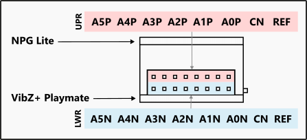
NPG Lite VibZ+ Playmate Connection#
Channel |
Pin |
Channel Connection |
|---|---|---|
Channel 1 |
A0P |
+ve of Channel 1 |
A0N |
-ve of Channel 1 |
|
Channel 2 |
A1P |
+ve of Channel 2 |
A1N |
-ve of Channel 2 |
|
Channel 3 |
A2P |
+ve of Channel 3 |
A2N |
-ve of Channel 3 |
|
Channel 4 |
A3P |
+ve of Channel 4 |
A3N |
-ve of Channel 4 |
|
Channel 5 |
A4P |
+ve of Channel 5 |
A4N |
-ve of Channel 5 |
|
Channel 6 |
A5P |
+ve of Channel 6 |
A5N |
-ve of Channel 6 |
|
REF |
Reference cable to REF |
|
CN/ CNB |
Common Negative |
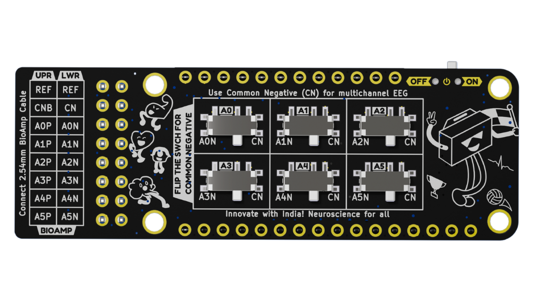
Using the Common Negative (CN)#
The Common Negative (CN) is an essential feature for multi-channel recordings like EEG, as it simplifies electrode placement and wiring. This new playmate replaces the previous solder jumpers with a convenient slide switch for instant configuration.
This is the biggest change: No soldering is required. Flipping the switch physically connects all negative inputs to the common line.
To configure the board to use the Common Negative, follow these steps:
Connect the Shared Electrode: Connect your single, common negative electrode snap cable to the dedicated CN pin header.
Locate the Switch: Find the
COMMON NEGATIVEslide switchs on the bottom of the board. The silkscreen text saysFLIP THE SWITCH FOR COMMON NEGATIVEand points directly to it.Enable CN mode: Flip the switch according to the negative channels input pins (A0N, A1N, A2N, A3N, A4N, and A5N). You now only need to connect your positive electrodes (e.g., A0P, A1P, etc.) and the single Common Negative electrode. You can leave all the individual negative pins (A0N-A5N) empty.
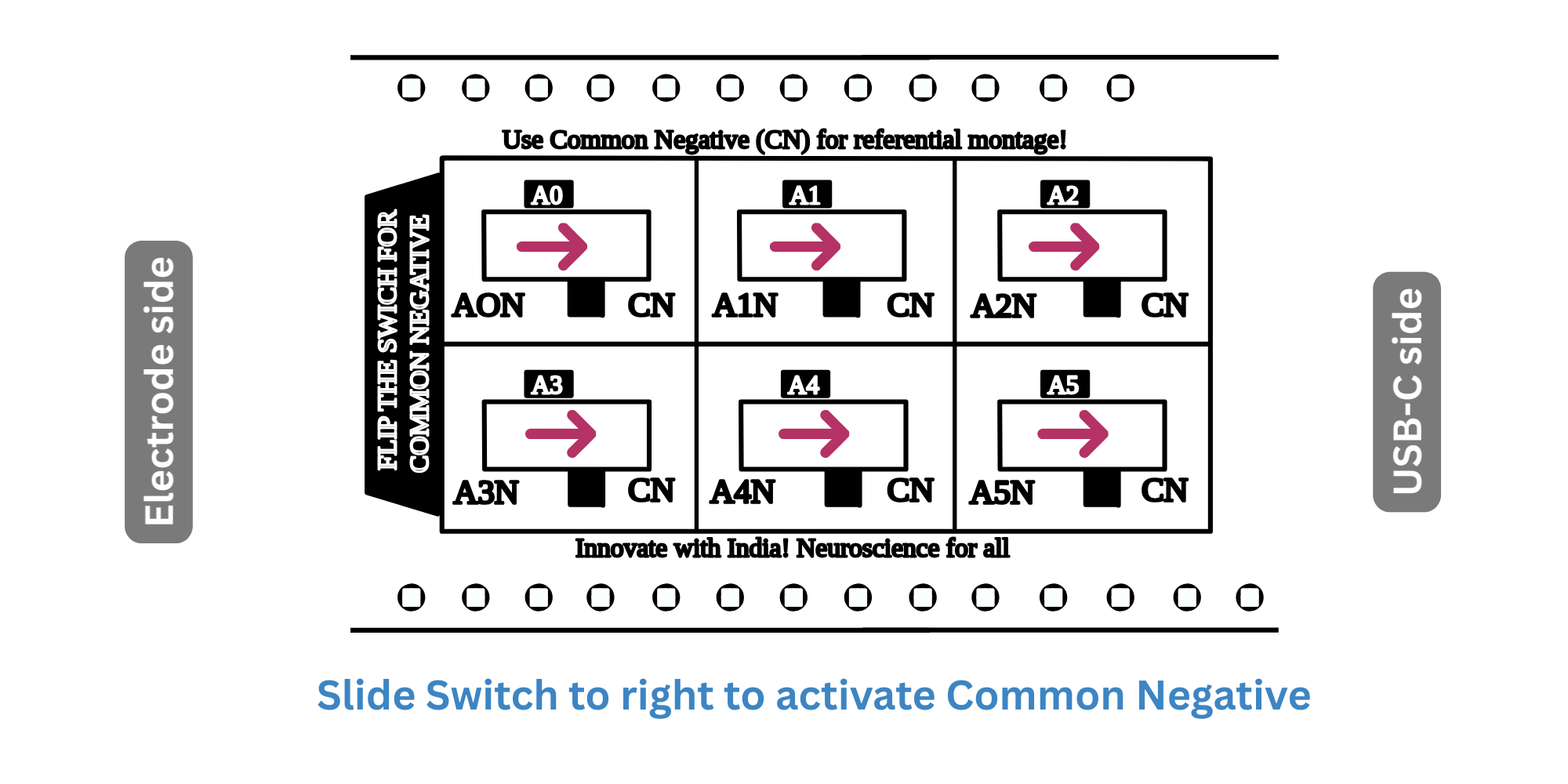
NPG Lite VibZ+ Playmate Common Negative#
Step 3: Place Gel Electrodes#
EMG (Electromyography)#
1-CH Setup: Place +ve and -ve cables of Channel 0 on the targeted muscle and REF cable on a bony part (back of the palm or elbow).
2-CH Setup: Place +ve, -ve cables of Channel 0 & 1 on the targeted muscles and 1 REF cable on a bony part.
3-CH Setup: Place +ve, -ve cables of Channel 0, 1 and 2 on the targeted muscles and 1 REF cable on a bony part.
General Multi-Channel Setup: For any multi-channel recording (2-CH or more), place the +ve cable for each respective channel on the targeted areas, then use only one REF cable and one CN (Common Negative) cable for all channels, placing them on your chosen reference points.
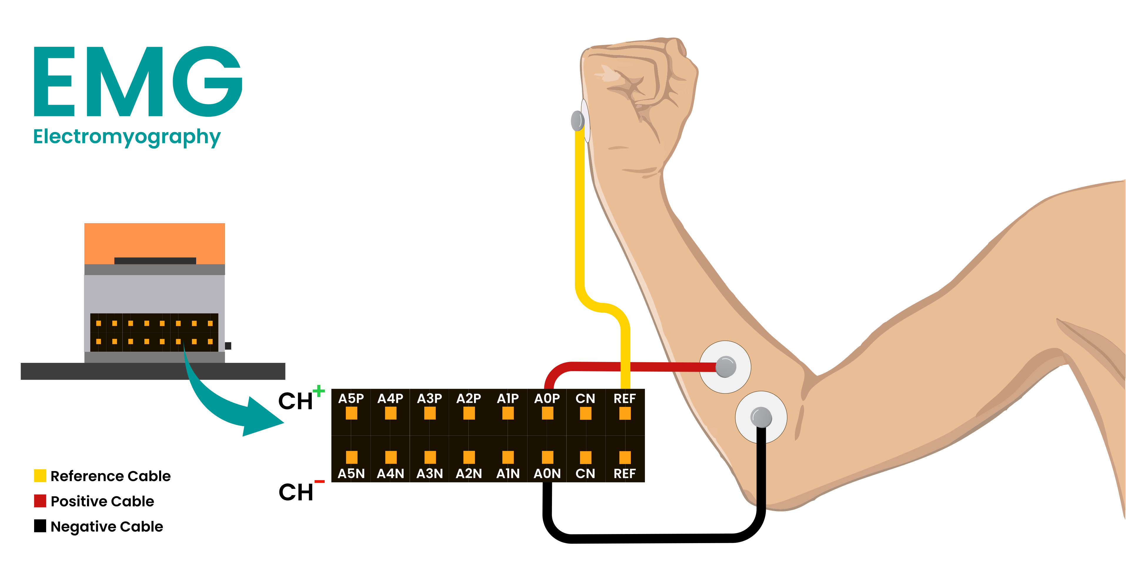
Connection for EMG#
ECG (Electrocardiography)#
1-CH Setup: Place -ve cable of Channel 0 on the left side of the chest, +ve cable just to its right, and REF cable on the right side of chest.
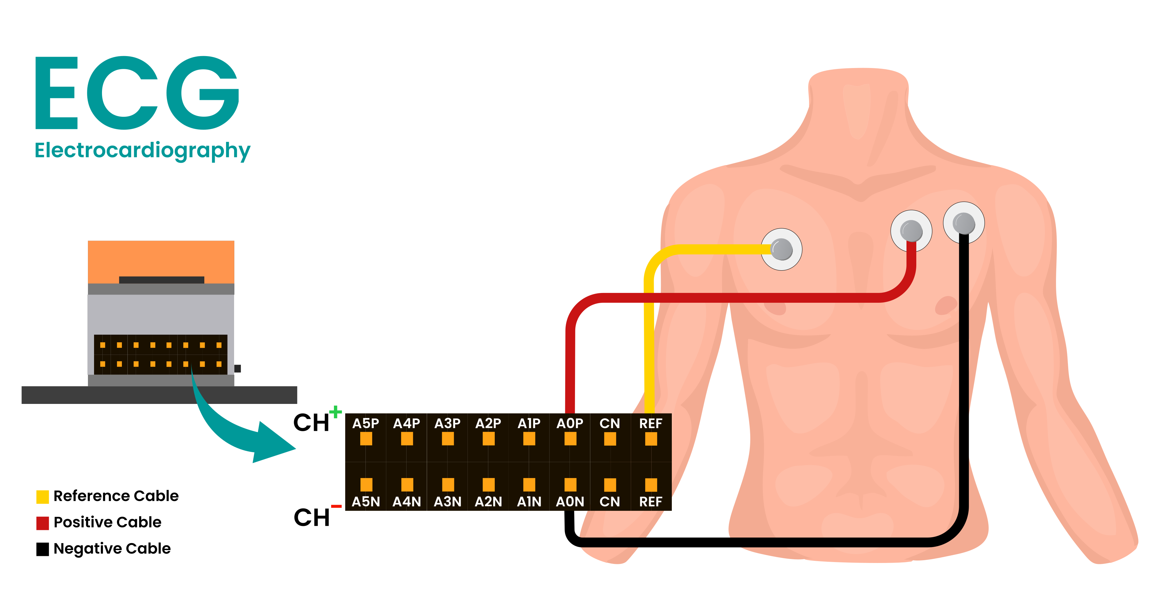
Connection for ECG#
EOG (Electrooculography)#
Horizontal Movement Recording
1-CH Setup: Place -ve cable of Channel 0 on the right side of your right eye, +ve cable on the left side of the left eye, and REF cable on the bony part at the back side of your earlobe.
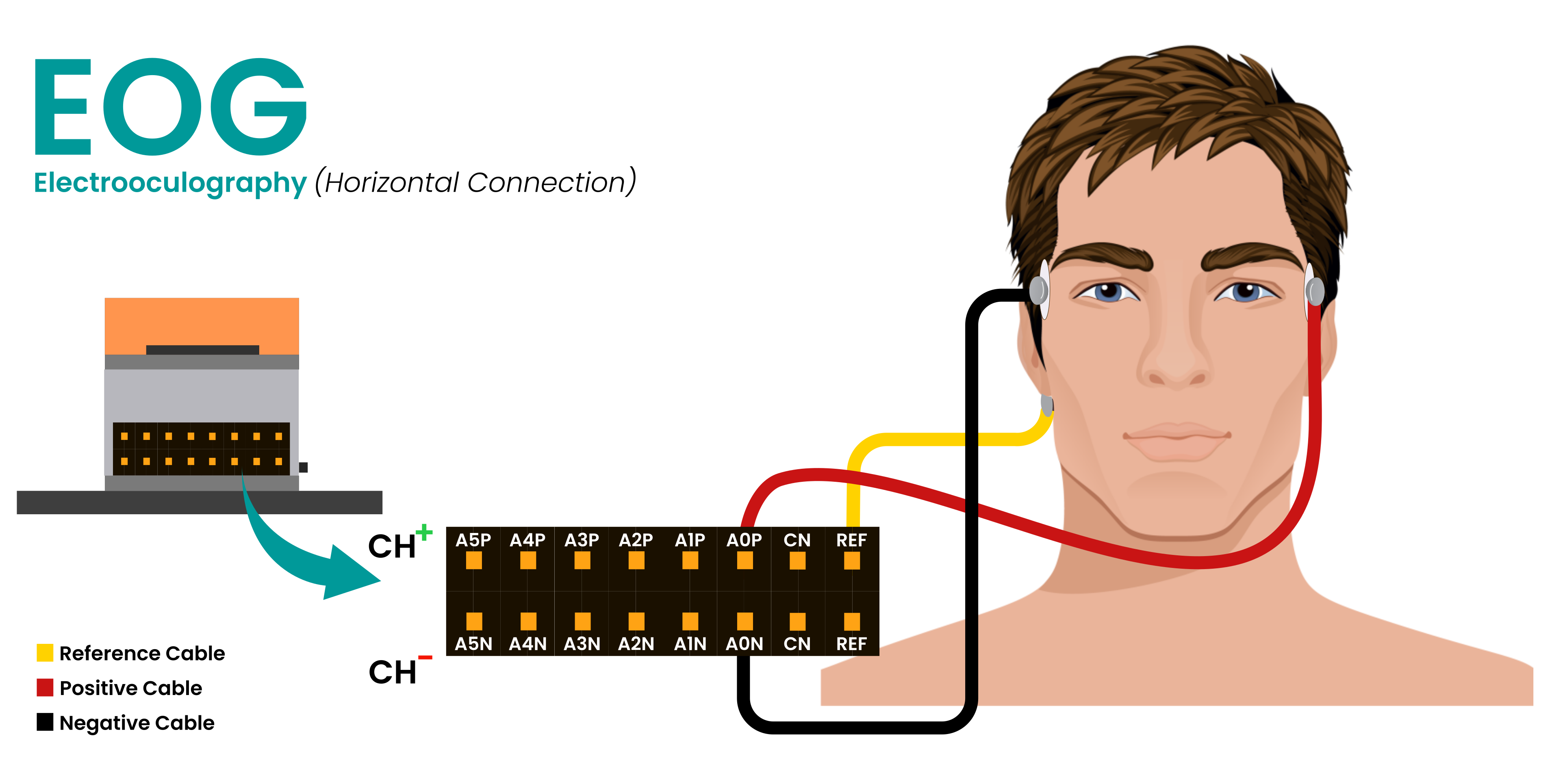
Connection for EOG Horizontal#
Vertical Movement Recording
1-CH Setup: Place the -ve cable of Channel 0 above either of your eyes, the +ve electrode below same eye, and the REF cable on the bony area behind your earlobe.
2-CH Setup: To record both horizontal & vertical eye movement together, follow the electrode placements mentioned above for Channels 0 and 1. Make sure to use just 1 REF cable.

Connection for EOG Vertical#
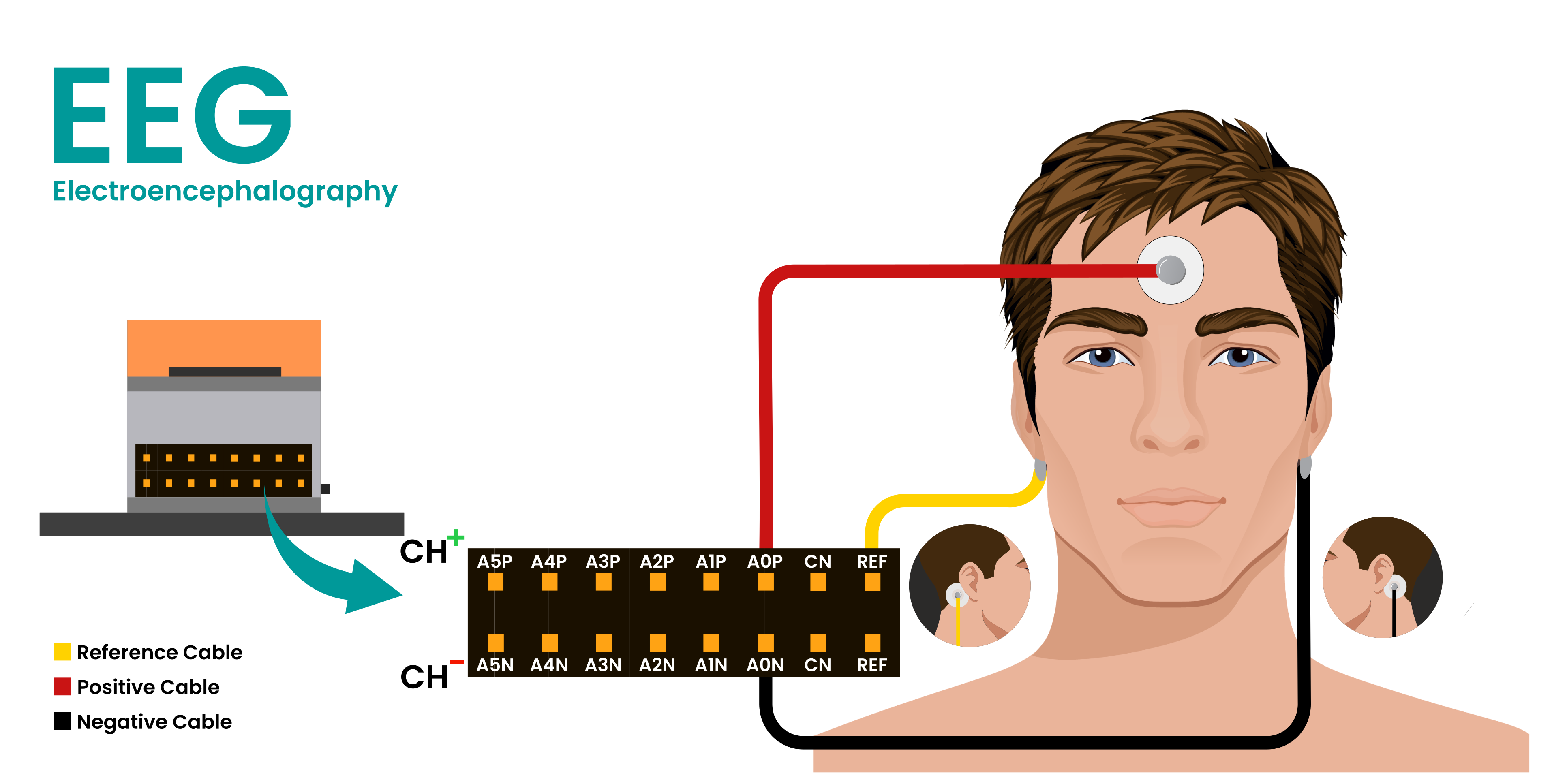
EEG (Electroencephalography)#
1-CH Setup: Place +ve cable of Channel 0 on the targeted area, REF and -ve cable on the bony part at the back of each earlobe. (refer to the International 10-20 system for recording EEG)
2-CH Setup: Place +ve cables of Channel 0 and 1 on the targeted area (refer to the International 10-20 system for recording EEG), 1 REF and 1 CN (Common Negative) cable on the bony parts at the back of each earlobe. Make sure the common negative switch for the respective channels is flipped accordingly, as per the information provided above.
3-CH Setup: Place +ve cables of Channel 0, 1 and 2 on the targeted area (refer to the International 10-20 system for recording EEG), 1 REF and 1 CN (Common Negative) cable on the bony part at the back of each earlobe. Make sure the common negative switch for the respective channels is flipped accordingly, as per the information provided above.
General Multi-Channel Setup: For any multi-channel recording (2-CH or more), place the +ve cable for each respective channel on the targeted areas, then use only one REF cable and one CN (Common Negative) cable for all channels, placing them on your chosen reference points. (refer to the International 10-20 system for recording EEG). Make sure the common negative switch for the respective channels is flipped accordingly, as per the information provided above.
Connection for EEG#
Step 4: Upload Firmware#
Follow the quick steps below to upload the firmware to your NPG Lite device:
For detailed firmware upload guide, visit: How to Flash Firmware on NPG Lite
Power ON NPG Lite by flipping the ON/OFF switch.
Connect it to Laptop/PC via USB-C cable.
Download the NPG Lite Flasher and run the app.
Select a firmware type, select your port, and flash it on your NPG Lite.
For a WiFi or BLE connection, remove the USB-C cable and enable Bluetooth or Wi-Fi on your laptop based on Firmware uploaded.
Step 5: Visualizing the signals#
Follow the steps below to view real-time biopotential signal data from your NPG Lite device:
Go to Chords Web
Click on
Visualize Now, navigate to theNPG-Lite, hit theConnectbutton and choose your device.You can see the biopotential signals in real-time.
For the detailed guide, visit: Chords Web Documentation
Explore features like play/pause data stream, apply filters, increase channel count, enable features for recording and downloading data in CSV format.
Battery Connection Guide#
Important
The battery connectors are polarity-sensitive and requires correct connection for safe operation. Incorrect connections will damage the device. Always verify connector polarity before connecting.
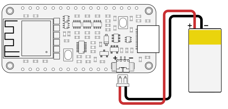
Option 1: Battery with 1.25mm PicoBlade Connector#
If you have purchased your battery from Upside Down Labs, or if have the same 1.25 mm PicoBlade connector, you can plug it directly into the battery connector on the NPG Lite.
While connecting the battery:
Make sure the Red Wire is connected to the
Positive (+) terminal.Make sure the Black Wire is connected to the
Negative (−) terminal.
This ensures the battery is connected with the correct polarity and prevents damage to the device.
Using Battery with 1.25mm PicoBlade Connector#
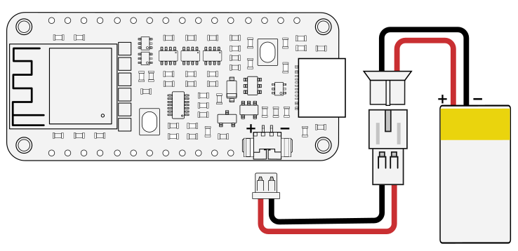
Option 2: Using a Battery with a JST-PH 2.0 mm Connector#
If your battery has a JST-PH 2.0 mm connector, you will need to use the adapter cable included in the NPG Lite kit to connect it.
Follow these steps:
Connect the battery to the adapter cable with JST connector: Match the wire colors -
Red to RedandBlack to Black.Connect the adapter cable to NPG Lite using the PicoBlade connector:
Make sure the Red Wire lines up with the
Positive (+) terminal.Make sure the Black Wire lines up with the
Negative (−) terminalon the NPG Lite connector.
This ensures the battery is connected with the correct polarity and prevents damage to the device.
Using Battery with JST-PH 2.0mm Connector#
Verifying Battery Polarity with a Multimeter#
If you are unsure about your battery’s polarity, verify it before connection:
Set your multimeter to measure DC Voltage (V⎓) and select 20V or higher range if it has manual dial.
Touch the red probe to the metal terminal of the connector where the red wire is attached.
Touch the black probe to the metal terminal where the black wire is attached.
Read the display:
Positive voltage (e.g., +3.6V to +4.2V): Polarity is correct. ✅
Negative voltage (e.g., -4.2V): Polarity is reversed. ❌
Danger
Safety Reminder: Double-check all connections before powering ON the device. Wrong battery connection will damage the device.