Module 6: Biopotential Signals [1]#
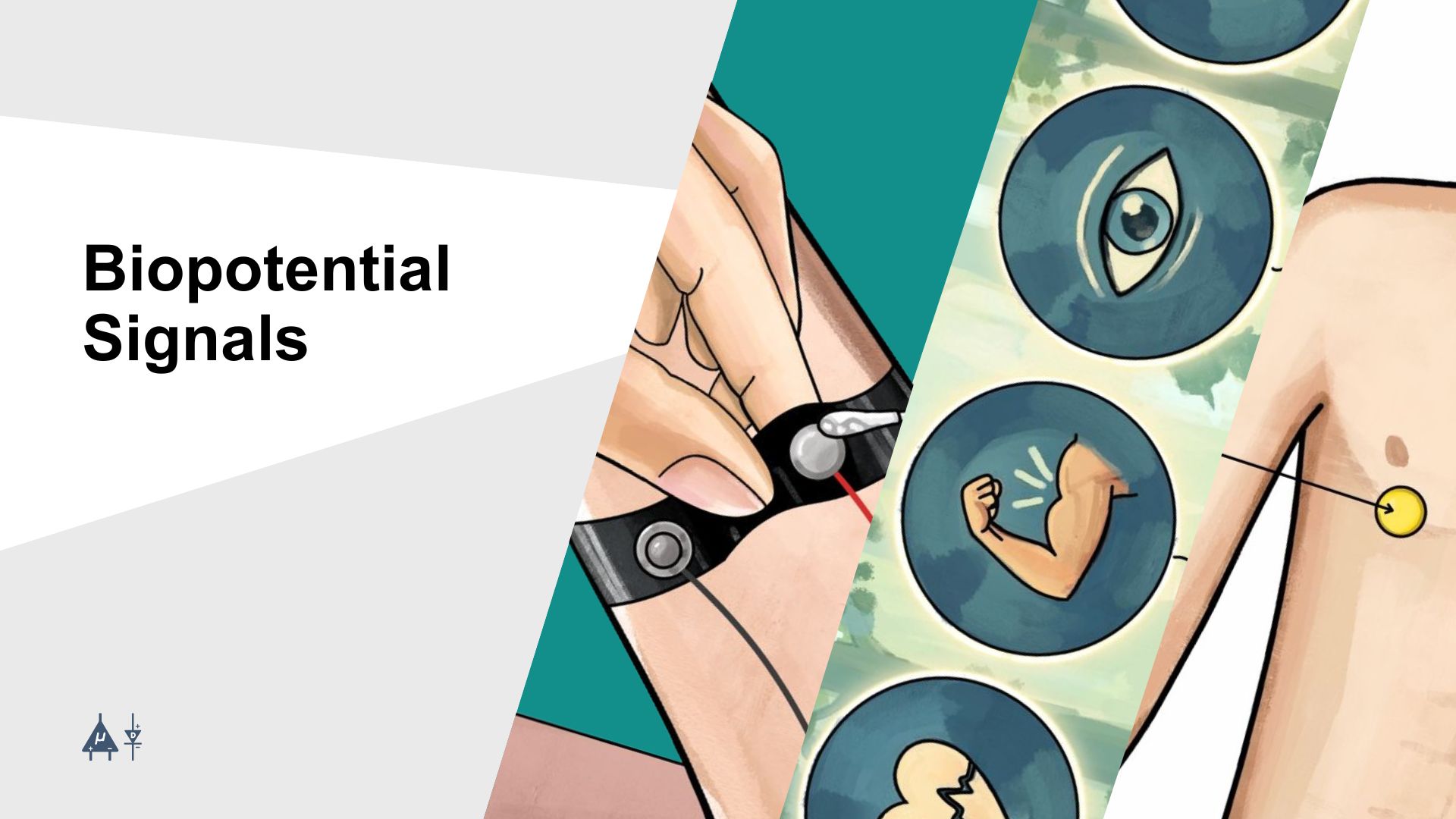
Biopotential signals are electrical signals generated within the body. They come from excitable cells found in the nervous system, muscles, and glands. When one of these cells gets stimulated, it triggers either an action potential or a graded potential. These electrical potentials form the basis of all measurable biopotential signals in the body.
Upside Down Labs has engineered multiple open-source BioAmp Hardware and BioAmp Software to measure and visualize the body’s biopotential signals. These signals include:

Biopotential signals#
Electrocardiography (ECG):
Electrocardiography (ECG) is a non-invasive diagnostic technique used to record the electrical activity of the heart over time. The heart generates electrical impulses that coordinate the contraction and relaxation of cardiac muscles, allowing blood to be pumped throughout the body. ECG electrodes placed on the skin detect these electrical signals and display them as waveforms (P wave, QRS complex, and T wave). This method is widely used to evaluate heart rhythm, detect arrhythmias, myocardial infarction, and other cardiac abnormalities. Amplitude ranges from 10µV to 5mV and frequency ranges from 0.05 to 100 Hz in normal ECG [2].
Electromyography (EMG):
Electromyography (EMG) is a technique used to measure and record the electrical activity produced by skeletal muscles during rest and contraction. When a motor neuron stimulates a muscle fiber, an electrical signal called a motor unit action potential is generated. EMG detects these signals using surface electrodes or needle electrodes inserted into the muscle. It is commonly used to assess neuromuscular disorders, muscle dysfunction, nerve damage, and diseases affecting motor control. Amplitude ranges from 0 to 10 mV (peak-to-peak) or 0 to 1.5mV (rms) and frequency ranges from 0 to 500 Hz in normal EMG [3].
Electrooculography (EOG):
Electrooculography (EOG) is a technique used to measure the electrical potential difference between the front (cornea) and back (retina) of the eye. As the eyes move, this potential difference changes and can be detected by electrodes placed around the eyes. EOG is commonly used to track eye movements, study visual behavior, and assess retinal function. It is also used in sleep research to identify rapid eye movement (REM) during sleep. Amplitude ranges from 100 to 3500 µV and frequency ranges from 0.1 to 20 Hz in normal EOG [4].
Electroencephalography (EEG):
Electroencephalography (EEG) is a method used to record the electrical activity of the brain produced by the synchronized activity of neurons, primarily in the cerebral cortex. Electrodes placed on the scalp detect small voltage fluctuations resulting from neuronal activity. EEG signals appear as brain waves (such as alpha, beta, theta, and delta waves). This technique is widely used in neuroscience and clinical settings to study brain function, diagnose neurological disorders such as epilepsy, monitor sleep stages, and investigate cognitive processes. Amplitude ranges from 10 to 100 µV and frequency ranges from 0.5 to 100 Hz in normal EEG [5].
BioAmp devices serve as a catalyst for the development of innovative Human-Computer Interface (HCI) and Brain-Computer Interface (BCI) projects, enabling people to explore the field of neuroscience.
6.1 How to measure biopotential signals#
Step 1: Prepare Skin - reduces skin impedance
Step 2: Place Electrodes - ensures correct signal location
Step 3: Connect Hardware - establishes electrical interface between electrodes and acquisition system
Step 4: Amplify & Filter - boosts weak signals and removes noise/interference
Step 5: Record & Visualize - captures signals for real-time monitoring and analysis
Step 6: Analyze - interprets data to extract meaningful physiological information
6.2 Skin Preparation Guide#
6.2.1 Why is skin preparation important?#
Proper skin preparation is crucial before recording any biopotential signal whether it is Electrocardiography (ECG), Electromyography (EMG), Electroencephalography (EEG), or Electrooculography (EOG).
Clean skin surface: Removes dead skin cells, oils, & other substances that increase skin impedance.
Reduce skin impedance: Improves the conduction of electrical signals from the body to the recording equipment and reduces impedance.
Electrode-skin contact: Ensures optimal contact between the electrodes and the skin surface.
Signal quality: Enhances the overall quality of recorded signals, providing clear & reliable data for analysis & improves the ability to capture subtle variations in biopotential signals.
Consistency in recordings: Reduces variability in signal quality, making it easier to make any Human-Computer Interface (HCI) and Brain-Computer Interface (BCI) projects or a real-world application.
Long term adhesion: Facilitates long-term adhesion & stable placement of electrodes to the skin during extended signal monitoring.
6.2.2 Steps to follow#
You can follow the steps given below to perform proper skin preparation:
Step 1: Identify the targeted area#
Identify the target area where the gel electrodes or BioAmp Bands will be placed for recording the biopotential signals.
Electrooculography (EOG)#
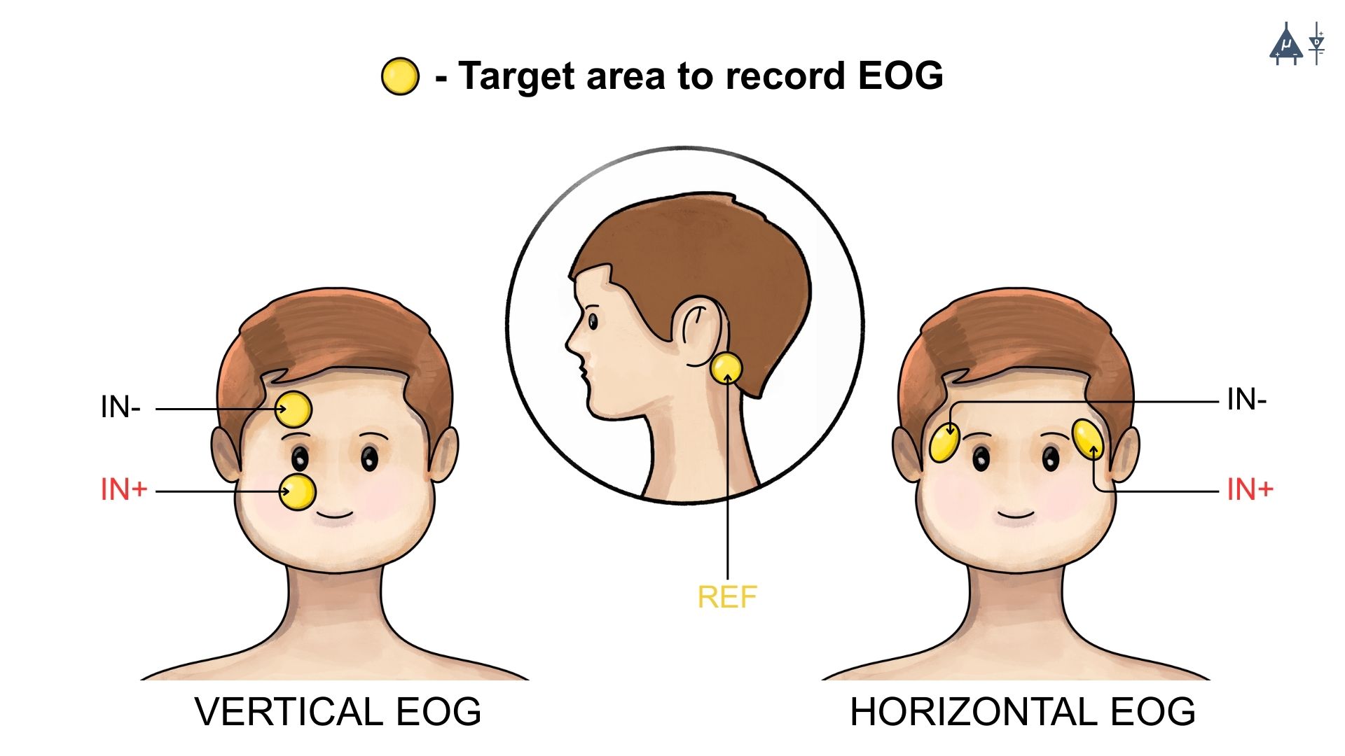
Target area to record EOG(single channel)#
Electromyography (EMG)#
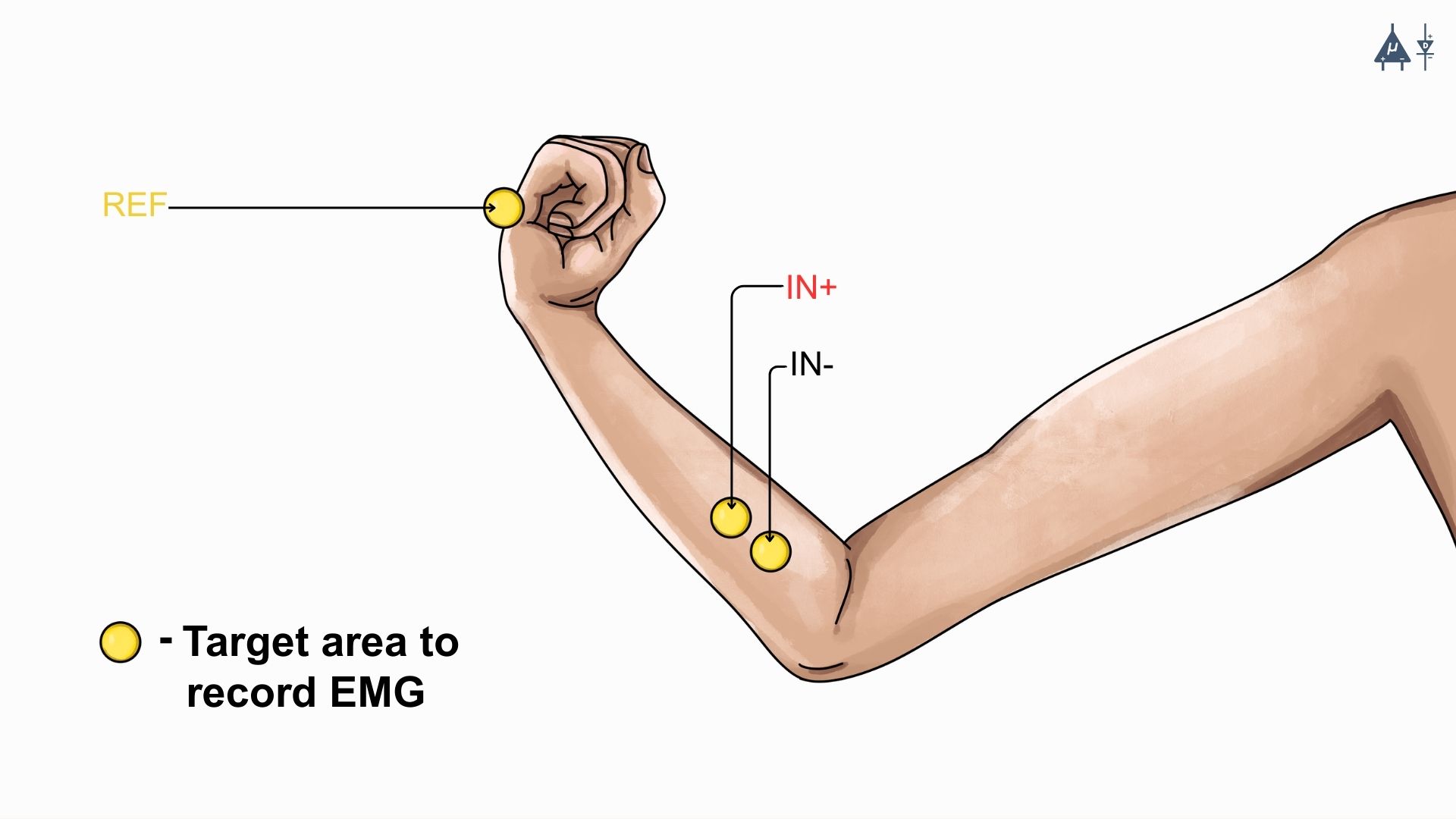
Target area to record EMG(single channel)#
Electrocardiography (ECG)#
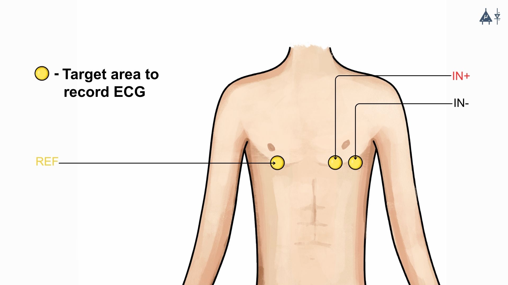
Target area to record ECG(single channel)#
Electroencephalography (EEG)#
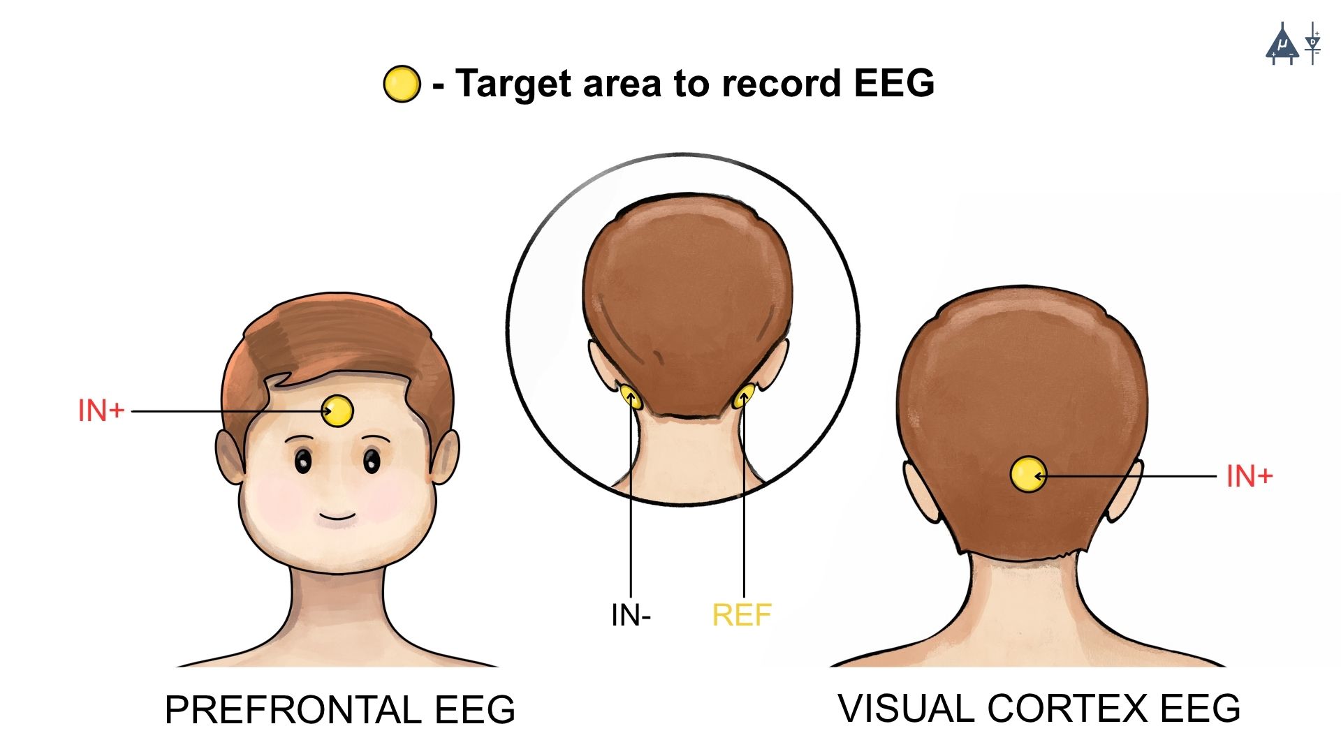
Target area to record EEG(single channel)#
Step 2: Apply NuPrep gel#
Take a small amount of NuPrep gel using a cotton swab and apply it to the targeted area.
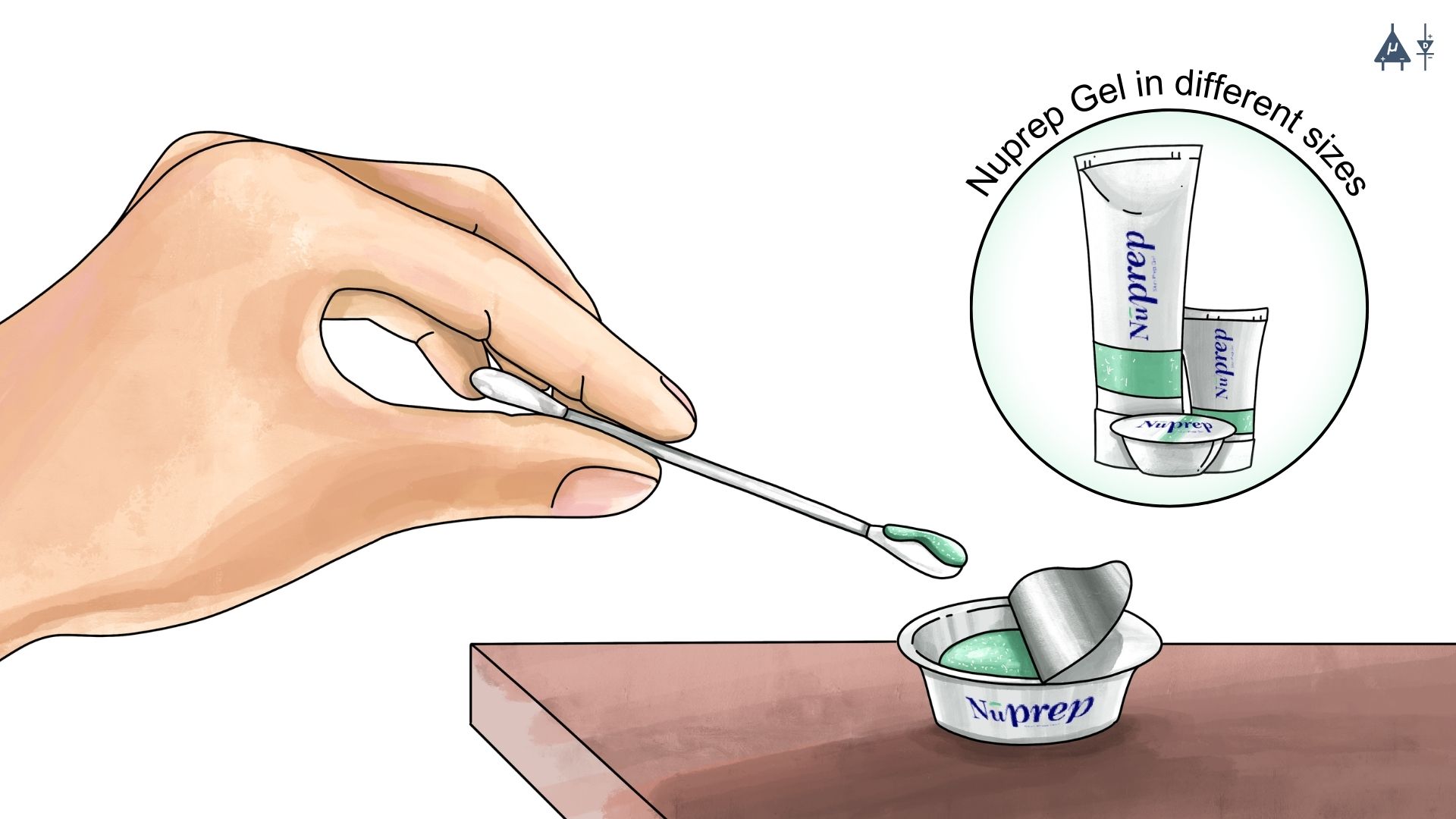
Applying NuPrep Gel#
Step 3: Clean the skin surface#
Use gentle, circular motions to rub the gel on the skin surface. This removes all the dead skin cells & improves conductivity.
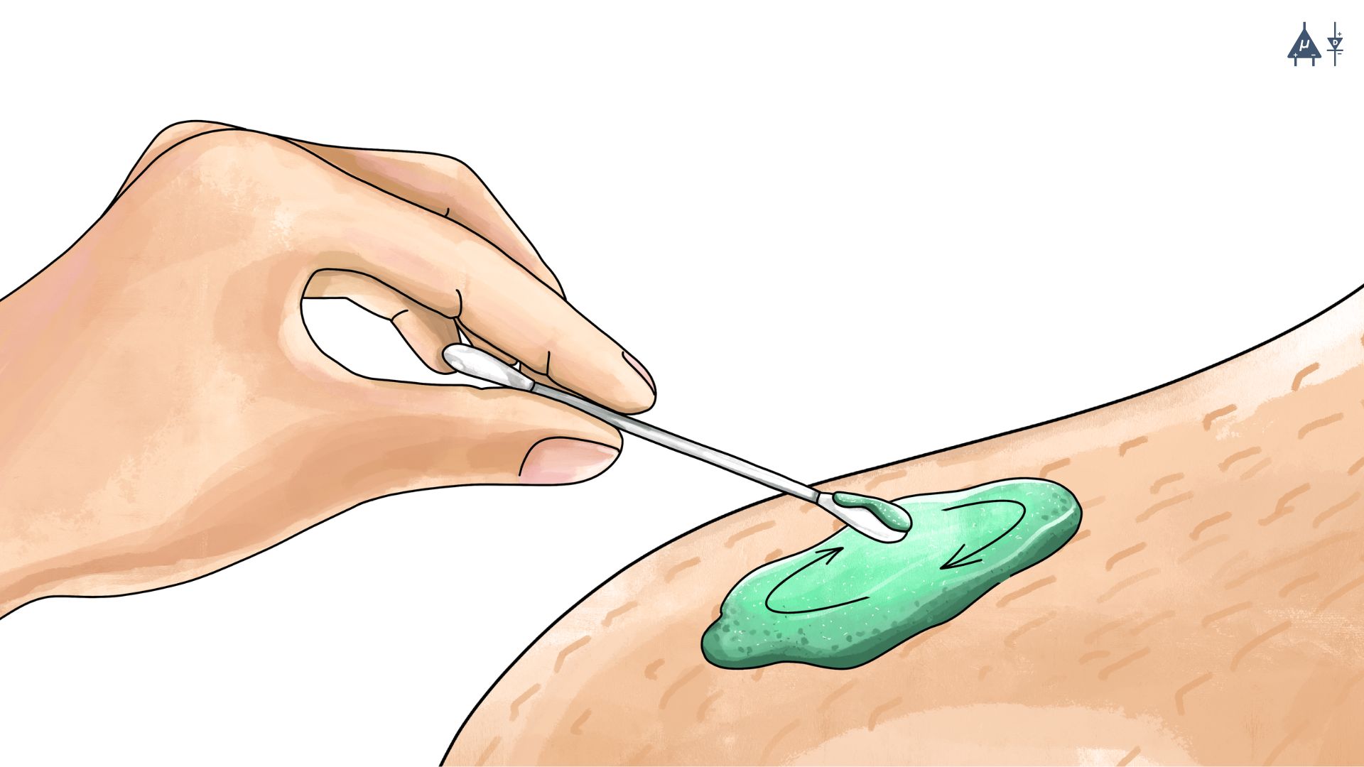
Rub the gel gently using the cotton swab#
Warning
Do not rub the gel for too long as it has abrasive properties and may cause skin redness and irritation.
Step 4: Wipe off the gel#
Wipe away excess gel with alcohol swabs or wet wipes.
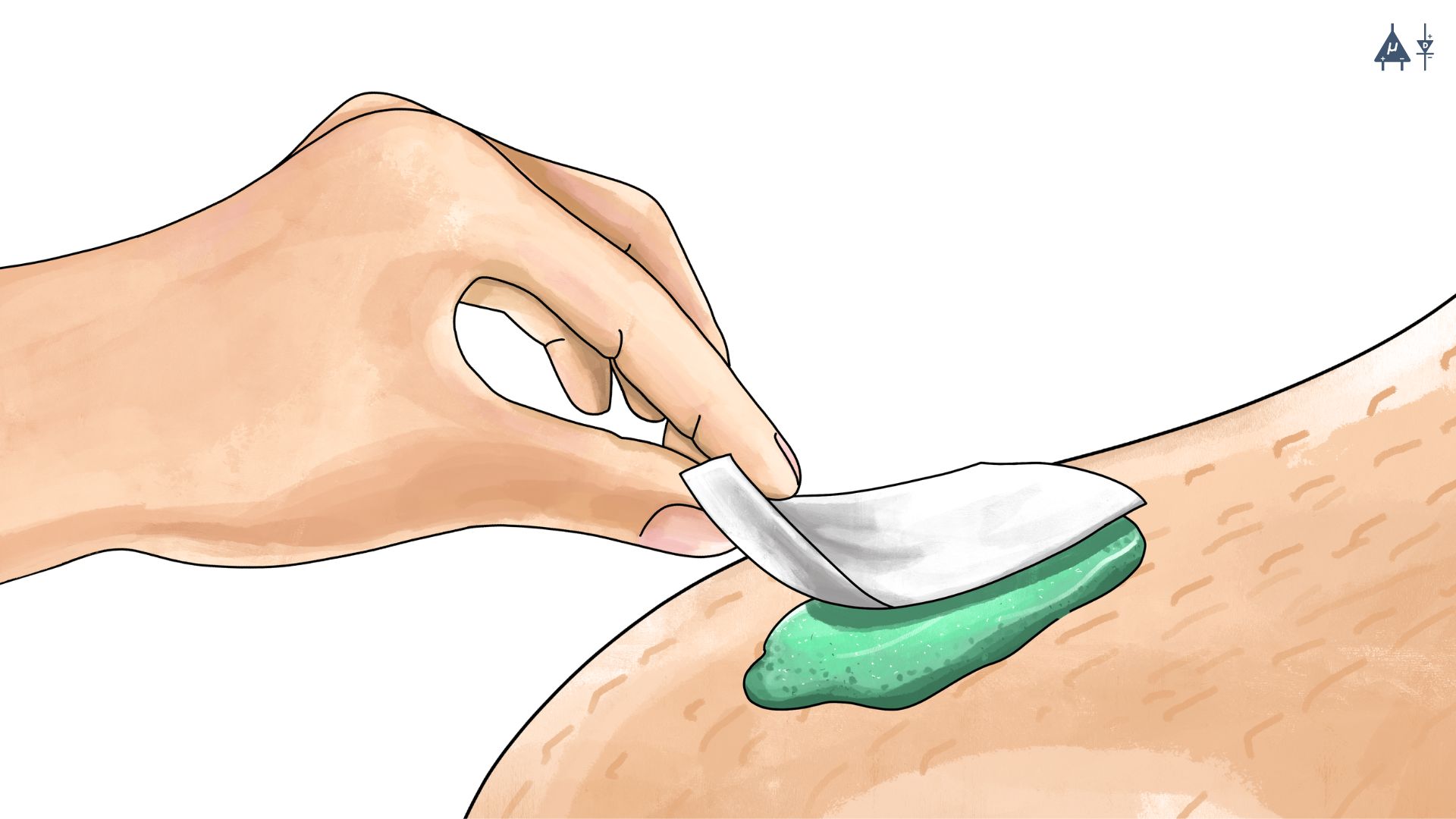
Wipe away excess gel#
Warning
Using alcohol swabs can dry out the skin, so do not use them if your skin is already dry.
Close your eyes while using the alcohol swabs for EOG recording else it may cause eye redness & irritation.
Step 5: Measuring the signals#
Now you can either use gel electrodes or BioAmp bands for the signal recording.
Using gel electrodes#
Connect the BioAmp cable to gel electrodes, peel the plastic backing from electrodes and place the IN+, IN- and REF cables according to your specific biopotential recording.
Placing gel electrodes on skin surface#
Note
While placing the gel electrodes on the skin, make sure to place the non-sticky tab of the electrode in the direction opposite to your hair growth. This allows you to remove the electrodes easily without pulling off much body hair.
For detailed info about using gel electrodes, please refer : Using Gel Electrodes
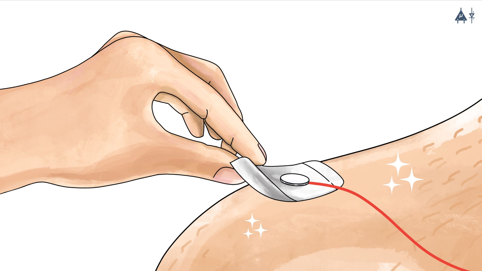
Using BioAmp bands#
Connect the BioAmp cable to your BioAmp band. Now apply a small amount of electrode gel or Ten20 conductive paste on the dry electrodes between the skin and metallic part of BioAmp cable. This improves the signal conductivity, enhancing overall signal quality.
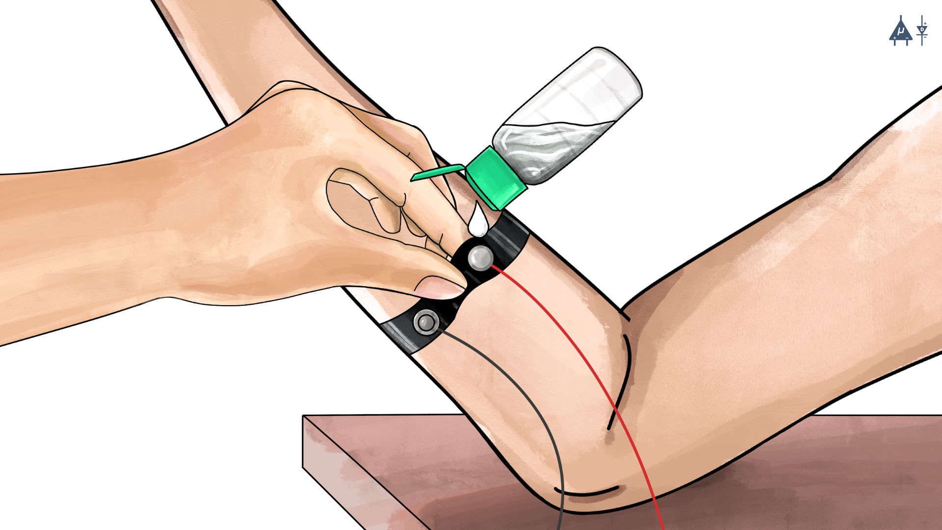
Method 1: Using gel for BioAmp bands#
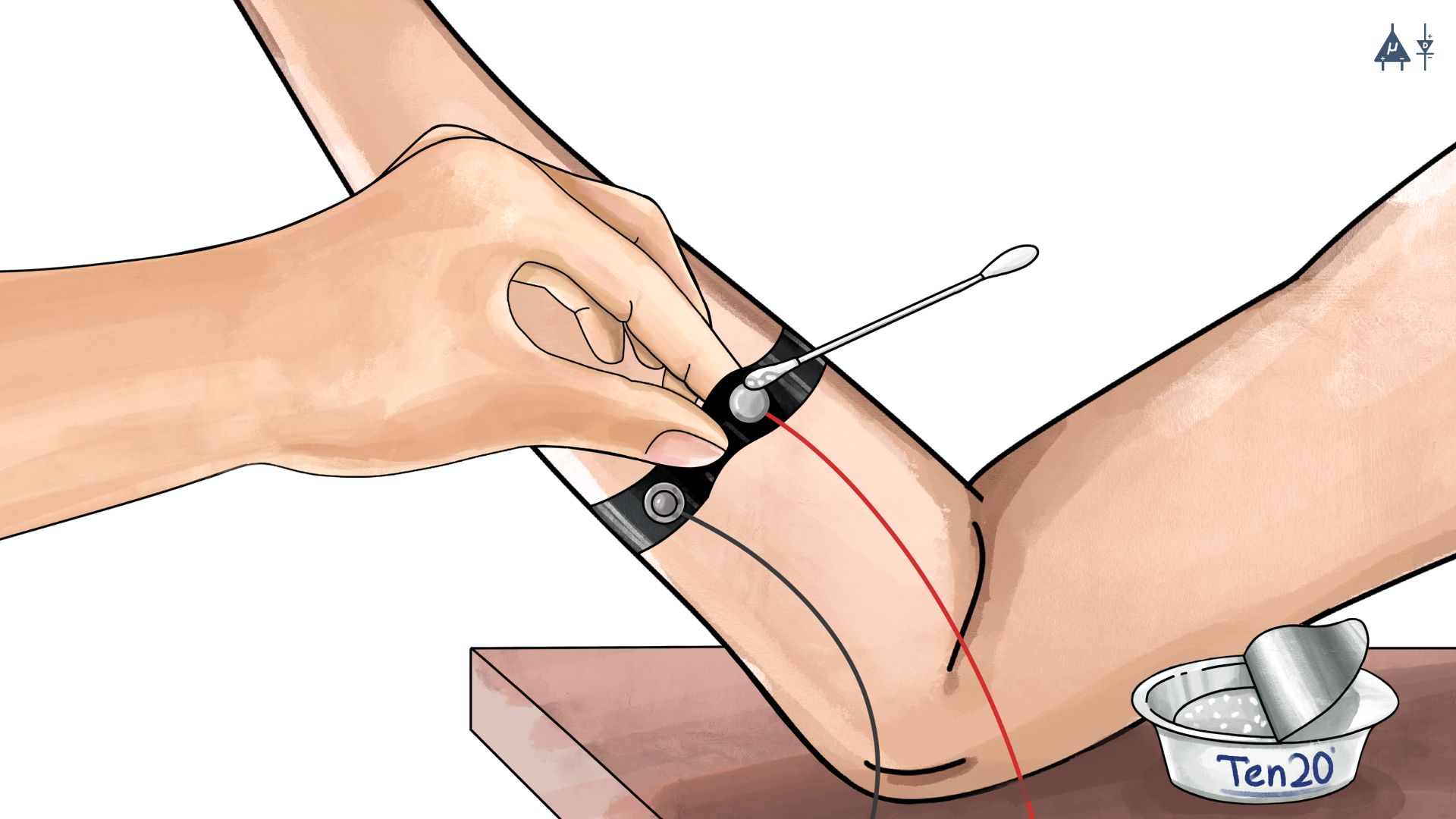
Method 2: Using Ten20 paste#
For detailed info about using BioAmp bands, please refer : Using BioAmp Bands
6.3 Basic electrode configuration#
6.3.1 What do IN+, IN-, and REF mean?#
Note
IN+ & IN- are two inputs of a special amplifier used by most biological recording systems, it’s called an instrumentation amplifier. An instrumentation amplifier (In-Amp) for biomedical devices is a high-gain, amplifier designed to extract a weak biological signal (the instrumentation voltage) while rejecting high levels of unwanted noise (the common-mode voltage).
IN+ (Non-inverting input)#
Positive input of the instrumentation amplifier
Placed directly on or very close to the tissue that generates the signal (muscle, heart, forehead, eye, etc.)
If the voltage here increases, the amplifier output increases.
This is the main signal input that captures the biopotential signal of interest.
IN- (Inverting input)#
Negative input of the instrumentation amplifier
Placed 2-10 cm away from IN+ (same muscle, same general area) OR on the opposite side (e.g., for EOG/ECG)
If the voltage here increases, the amplifier output decreases (it is inverted).
Output of the amplifier is proportional to the difference between IN+ and IN- {Output = Gain × (IN+ − IN−)}.
Note
By amplifying only the differential voltage (the difference between inputs) and rejecting common voltages, the instrumentation amplifier effectively suppresses electromagnetic interference (EMI) and noise.
REF (Mid-supply or DRL)#
Placed at a neutral, electrically silent site.
Placed on bony area far from the signal source (elbow, wrist bone, ankle)
Removes common noise like 50/60 Hz noise that appears on both IN+ and IN- .
Tip
For better signal acquisition guide, refer: Tips for best signal acquisition
Note
For some system REF can mean common negative or ground electrode, for BioAmp we use REF to denote mid-supply electrode which is same as BIAS on other systems.
6.4 Summary#
In this module, we learned about biopotential signals. This module explained the steps of measuring biopotentials, including skin preparation and electrode placement. We also studied how instrumentation amplifier recording works using IN+, IN-, and REF to get clean, noise-free signals. In the next module you are going to learn how to record EMG signals at home by using our budget friendly BioAmp hardwares and open source softwares.
Warning
These recordings are for educational purposes only and are not intended for medical diagnosis.