Muscle (EMG) BioAmp Firmware#
What is Electromyography (EMG)?#
Electromyography (EMG) [1] is a technique for evaluating and recording the electrical activity produced by skeletal muscles. EMG is performed using an instrument called an electromyograph to produce a record called an electromyogram. An electromyograph detects the electric potential generated by muscle cells when these cells are electrically or neurologically activated. The signals can be analyzed to detect abnormalities, activation level, or recruitment order, or to analyze the biomechanics of human or animal movement. In computer science, EMG is also used as middleware in gesture recognition towards allowing the input of physical action to a computer as a form of human-computer interaction.
To know more about EMG visit here.
Who is this for?#
Anyone who’s using the BioAmp Muscle Hardware for the very first time — whether you’re a student, hobbyist, educator, or just curious. No experience needed!
👉 To learn about our BioAmp Hardware checkout the hardware page.
Step-by-Step Setup Guide#
With the hardware in your hands, you’re just a few steps away from unlocking its full potential — let’s get the software set up!
Step 1: Downloading GitHub Repository for Hardware#
This is the code your Arduino needs to read Muscle (EMG) signals.
You have two easy ways to get the code that will help you read your EMG signals:
Simply Download (recommended for beginners)
Go to the GitHub page: Muscle BioAmp Arduino Firmware
Click the green “Code” button > Download ZIP
Unzip the folder and save it somewhere easy to find.
Clone using Git (for tech-savvy users)
Install Git for your OS: https://git-scm.com/
Clone this GitHub repository using
git clone https://github.com/upsidedownlabs/Muscle-BioAmp-Arduino-Firmware
Step 2: Application Required#
Before you start using the kit, please download or open the following:
Arduino IDE
We need Arduino IDE to upload code to your Arduino board
Link to download IDE for your OS: https://www.arduino.cc/en/software
Chords Website
We will use Chords Website to visualize the Muscle Signals!
Open this website: Chords Web
Step 3: Connect Your Hardware#
Plug the Hardware into your Arduino UNO using jumper wires.
Follow the exact wiring diagram from the hardware documentation of the hardware you are using.
Hardwares that are compatible with Muscle BioAmp Firmware:
It’s just like putting together a puzzle!
Step 4: Skin Preparation and Electrodes Placement#
There are two ways use Gel Electrods or Muscle BioAmp Band.
Using Gel Electrodes:
Prepare your skin
Choose the area where you’ll place the electrodes.
Clean the skin using an alcohol swab or Nuprep Gel to remove oils and dead cells — this improves signal clarity.
Note
Need help with skin prep? Check out the full guide here: Skin Preparation Guide
Attach the wires to the electrodes, then attach the electrodes to the skin
IN+(positive): Place this on your inner forearm.IN–(negative): Place 2–3 cm away from IN+, following the direction of the muscle fibers.REF(reference): Place on a bony or electrically neutral area, such as the elbow bone or wrist joint.Refer to the diagram below for accurate placement.
Make sure the sticky side makes firm contact with the skin for best performance.
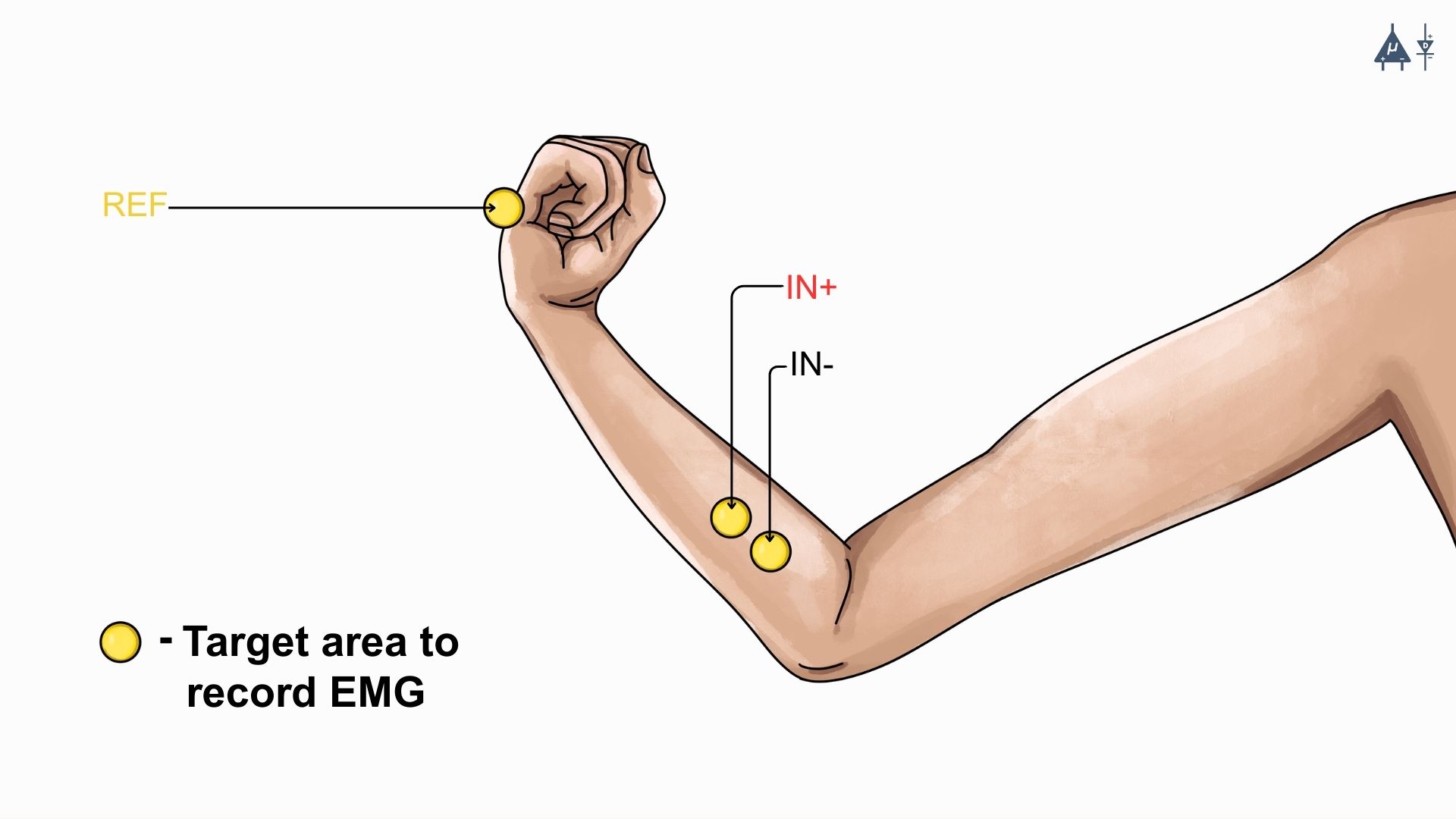
EMG Placement#
Using Muscle BioAmp Band:
Connect the BioAmp cable to Muscle BioAmp Band in a way such that IN+ and IN- are placed on the arm near the ulnar nerve & REF (reference) on the far side of the band.
Now put a small drop of electrode gel between the skin and metallic part of BioAmp cable to get the best results
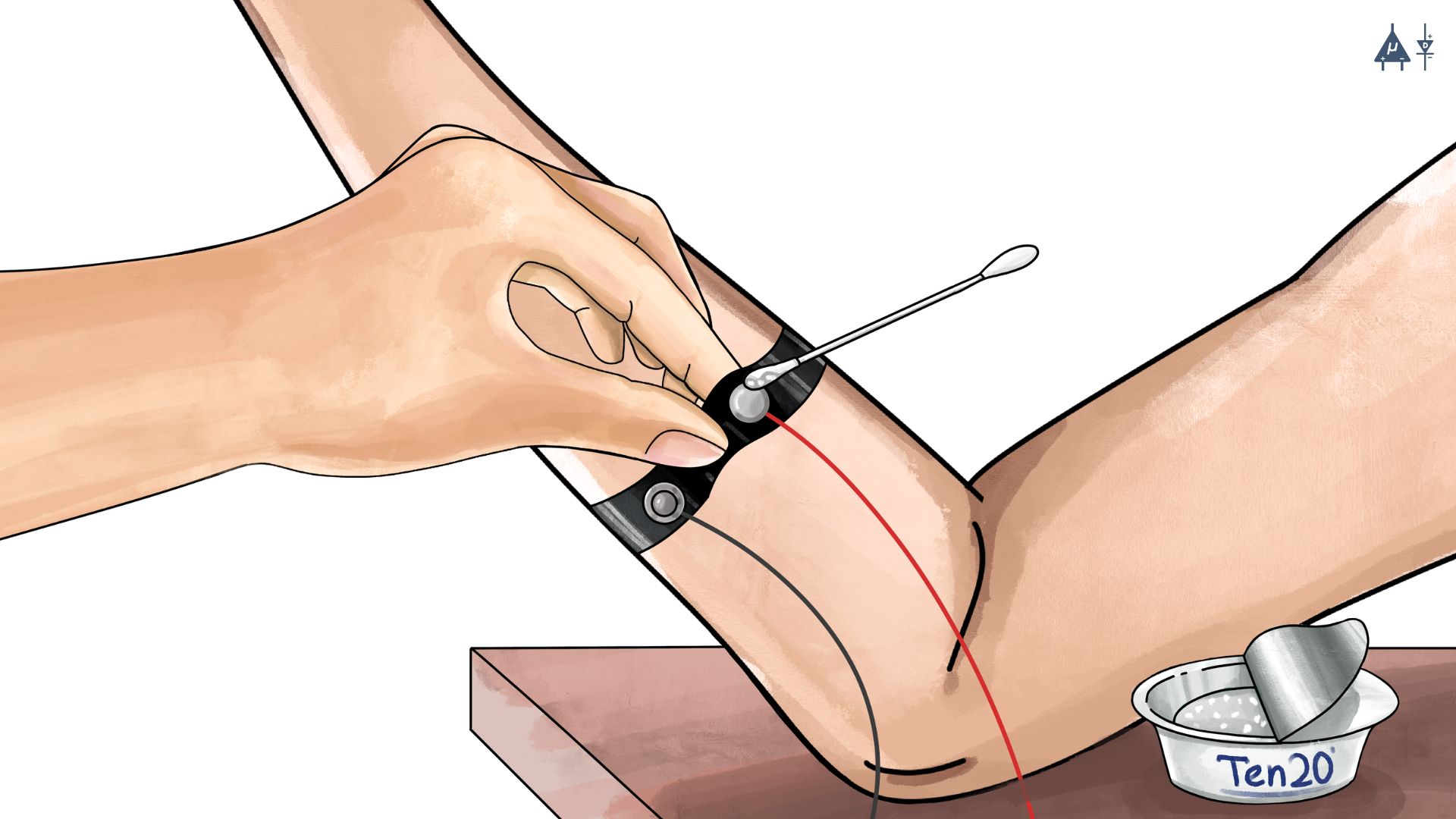
Muscle BioAmp Band Placement#
Step 5: How to upload the Code to Arduino#
Open the folder you downloaded: Muscle-BioAmp-Arduino-Firmware
Inside that, you’ll find several subfolders.
Pick the folder for the experiment you want to try. (For beginners: start with the first one and move step-by-step through the others for a better learning experience )
Inside that folder, open the .ino file using Arduino IDE
For example:
To try raw signal: open
01_Fixed_Sampling.inoTo try filtered signal: open
02_EMG_Filter.ino
Note
You’ll find all the experiments listed below, each with step-by-step instructions. Just scroll to the one you’re working on to get started with the right setup.
Connect Your Arduino
Plug your Arduino board into your computer’s USB port using the USB cable.
Wait for the operating system to install any required USB drivers.
In Arduino IDE:
Go to Tools > Board > Arduino UNO choose the model of your board (e.g., “Arduino Uno” or “Arduino Nano” if you wired to a Nano)
Go to Tools > Port > [select the correct COM port]
Verify (Compile) the Sketch
Click the “✔️ Verify” button (or press
Ctrl + R).Wait for “Done compiling.” If errors appear, double-check you opened the correct .ino file.
Click the ✓ Upload (or press
Ctrl + U) button to send the code to your Arduino.The IDE will compile again and then send the code to your board.
The onboard LED labeled “L” may blink during upload. When you see “Done uploading”, the new firmware is running.
Open Serial Monitor and Serial Plotter (Optional)
For serial monitor and plotter, we recommend using Chords Web. However, if you’re learning to develop, you might also find these options useful.
For Serial Monitor: In the IDE, click Tools → Serial Monitor (or press
Ctrl + Shift + M).Ensure the baud rate at the bottom right of the Serial Monitor is set to
115200(or whatever the sketch’s Serial.begin(115200); line specifies).You should start seeing lines of numbers. Those are your readings.
For Serial Plotter: In the IDE, click Tools → Serial Plotter.
You should start seeing plotting of graph and visualize the waves.
Important
Remember to close the Serial Monitor & Serial Plotter in Arduino IDE before starting the Chords Visualizer.
Step 6: Visualize Your Muscle Signals!#
Open the website: Chords Web
Click: Visualize Now → then choose Serial Wizard.
Select the correct COM port (same one from Arduino IDE).
Click Connect.
Important
Always disconnect your laptop charger while testing. Why? Charging can introduce 50 Hz noise that affects the signal.
🎉 Now move your hand or clench your fist — you’ll see real-time EMG waves on the screen!
Let’s explore all the experiments step by step#
1. Fixed Sampling
1. Program Purpose & Overview
The Fixed Sampling sketch demonstrates continuous, regular‐interval sampling of raw EMG (electromyography) voltage readings from a Muscle BioAmp sensor. By reading analog voltage at a fixed rate (for example, 500 samples per second), you get a stable stream of unfiltered EMG data. This acts as the foundation for every subsequent signal-processing demonstration. Beginners can see what “raw” muscle signals look like before any filtering or envelope detection.
2. How It Works
Initialize the Sensor Pin
The sketch sets an Arduino analog input pin (e.g., A0) to read voltage values from the BioAmp sensor.
Set Sampling Rate
A timer (using
micros()ordelayMicroseconds()) ensures that we callanalogRead(A0)at a precise interval.For instance, reading every 2 millisecond → ~500 Hz sampling.
Print Raw Values
The user sees raw voltage fluctuations corresponding to muscle contractions.
Loop Forever
The
loop()continues indefinitely, constantly reading and printing.
3. Perform the Hardware
Refer to wiring as per instructions given in Connect Your Hardware
4. Firmware Upload
For this project, navigate to the repository folder (Muscle-BioAmp-Arduino-Firmware/01_Fixed_Sampling) and select
01_Fixed_Sampling.ino.To upload firmware, refer to How to upload the Code to Arduino
5. Visualize your signal
Follow the steps given in Visualize Your Muscle Signals!
6. Running & Observing Results
No Muscle Contraction → Raw values will show noise like spikes.
Flex Muscle → Suddenly values jump up or down.
Relax Muscle → Values return toward the midpoint.
Note
For a detailed guide, visit our Instructables page: Visualizing Muscle Signals (EMG)
2. EMG Filter
1. Program Purpose & Overview
The EMG Filter sketch acquires raw EMG data from a Muscle BioAmp sensor and applies a band‐pass filter (approximately 74.5 Hz–149.5 Hz) to isolate the muscle signal. By removing low‐frequency motion artifacts and high‐frequency noise, you get a cleaner, more stable EMG stream. This filtered output is ideal for downstream tasks like envelope detection or device control.
2. How It Works
Initialize the Sensor Pin
The sketch configures an Arduino analog input pin (e.g., A0) to read voltage values from the BioAmp sensor.
Set Sampling Rate
A timer (using
micros()ordelayMicroseconds()) ensures that we callanalogRead(A0)at a precise interval.For instance, reading every 2 millisecond → ~500 Hz sampling.
Apply Band‐Pass Filter
Each new analog reading is passed through a digital filter (typically implemented via FIR or IIR coefficients). The filter code maintains small arrays (buffers) of recent inputs and outputs, computing a weighted sum to produce a filtered value.
Print Raw Values
The resulting filtered floating‐point value is sent over Serial (e.g., Serial.print(filteredValue);), so you see a smooth EMG waveform.
Loop Forever
The
loop()repeats indefinitely: read → filter → print → delay to maintain sampling rate.
To learn more about filters and how to generate new filters, visit: https://docs.scipy.org/doc/scipy/reference/generated/scipy.signal.butter.html
3. Perform the Hardware
Refer to wiring as per instructions given in Connect Your Hardware
4. Firmware Upload
For this project, go to the repository folder (Muscle-BioAmp-Arduino-Firmware/02_EMG_Filter) and select
02_EMG_Filter.ino.To upload firmware, refer to How to upload the Code to Arduino
5. Visualize your signal
Follow the steps given in Visualize Your Muscle Signals!
6. Running & Observing Results
No Muscle Contraction → Filtered output hovers near zero (small baseline noise).
Flex Muscle → You see smooth spikes in the filtered value (e.g., jumps to 0.05–0.10), with noise removed.
Relax Muscle → Filtered output returns to baseline smoothly, with minimal fluctuation.
3. EMG Envelope
1. Program Purpose & Overview
The EMG Envelope sketch reads raw EMG data, applies a band‐pass filter (≈ 74.5 Hz–149.5 Hz), then computes the envelope of the filtered signal. The envelope is a smoothed, rectified representation of muscle activation amplitude. It is commonly used in prosthetic control, robotics, and biomedical research to detect when a muscle is contracting and with what strength.
2. How It Works
Initialize the Sensor Pin
Read analog values on A0 at a fixed rate (e.g., 500 Hz) and pass each sample through a digital band‐pass filter (implemented via FIR or IIR coefficients).
Full‐Wave Rectification
Convert the filtered sample to its absolute value:
float rectified = abs(filteredValue);
Low‐Pass (Smoothing) Filter
Apply a simple moving average or exponential moving average to rectified to generate a smooth envelope:
static float prevEnvelope = 0;

float alpha = 0.1;

float envelope = alpha * rectified + (1 - alpha) * prevEnvelope;

prevEnvelope = envelope;
Print Envelope
Send the smoothed envelope value via Serial.
Loop Forever
The
loop()repeats indefinitely: read → filter → rectify → smooth → print → delay to maintain sampling rate.
3. Perform the Hardware
Refer to wiring as per instructions given in Connect Your Hardware
4. Firmware Upload
For this project, navigate to the repository folder (Muscle-BioAmp-Arduino-Firmware/03_EMG_Envelope) and select
03_EMG_Envelope.ino.To upload firmware, refer to How to upload the Code to Arduino
5. Visualize your signal
Follow the steps given in Visualize Your Muscle Signals!
6. Running & Observing Results
Relaxed Muscle → Envelope values stay near zero.
Slow Flex → Envelope gradually increases.
Strong Flex → Envelope peaks higher.
Envelope changes smoothly, making thresholds easy to detect.
Note
For a detailed guide, visit our Instructables page: Recording Publication Grade Muscle Signals Using BioAmp EXG Pill
4. Claw Controller
1. Program Purpose & Overview
The Claw Controller sketch uses EMG envelope data to drive a servo‐powered “claw” mechanism. As you flex your muscle, the servo closes the claw; when you relax, it opens. This demonstrates a simple bio‐controlled prosthetic or robotic gripper, illustrating how EMG signals can be translated into mechanical movement.
2. How It Works
Acquire & Filter (as in EMG_Filter) to obtain a filtered EMG value at ~500 Hz.
Compute Envelope (as in EMG_Envelope) by rectifying and smoothing the filtered sign
Map Envelope to Servo Angle
Adjust scaling constants so that typical muscle contractions map to 0–180°.
int angle = map(envelope * 1000, 0, 100, 0, 180);
Servo Control
#include <Servo.h>
Servo clawServo;
...
clawServo.attach(9);  // PWM pin 9
clawServo.write(angle);
Loop Forever
The
loop()repeats indefinitely: read → filter → envelope → map → write to servo → delay.
3. Perform the Hardware
Refer to wiring as per instructions given in Connect Your Hardware
Additionally connect:
Servo VCC (Red) → Arduino 5 V (or external 5 V supply for stable power)
Servo GND (Black/Brown) → Arduino GND (and common ground if external supply used)
Servo Signal (Yellow/Orange) → Arduino D9 (PWM pin)
4. Firmware Upload
For this project, navigate to the repository folder (Muscle-BioAmp-Arduino-Firmware/04_Claw_Controller) and select
04_Claw_Controller.ino.To upload firmware, refer to How to upload the Code to Arduino
5. Visualize your signal
Follow the steps given in Visualize Your Muscle Signals!
6. Running & Observing Results
Relaxed Muscle → Servo rests at minimum angle (often 0° or defined “open” position).
Moderate Flex → Servo moves partway (e.g., 90°).
Strong Flex → Servo moves to maximum (180°, claw fully closed).
Relax → Servo returns to open angle. Adjust mapping if directions are inverted.
Note
For a detailed guide, visit our Instructables page: Controlling Servo Claw With Muscle Signals Using Muscle BioAmp Shield
5. Servo Control
1. Program Purpose & Overview
The Servo Control sketch is a generic demonstration of using EMG envelope amplitude to drive a single servo motor. Instead of a claw mechanism, it maps envelope directly to any servo’s rotation angle. This example can be repurposed to control robotic arms, wheels, or any servo‐driven structure based on muscle effort.
2. How It Works
Acquire & Filter EMG on A0 at ~500 Hz (same filter as EMG_Filter).
Compute Envelope by rectifying and smoothing the filtered value.
Map Envelope to Servo Angle
Tweak constants so typical contractions cover the desired servo range.
int angle = map(envelope * 1000, 0, 100, 0, 180);
Servo Control
#include <Servo.h>
Servo myServo;
...
myServo.attach(9);
myServo.write(angle);
Loop Forever
The
loop()repeats indefinitely: read → filter → envelope → map → write → delay.
3. Perform the Hardware
Refer to wiring as per instructions given in Connect Your Hardware
Additionally connect:
Servo VCC (Red) → Arduino 5 V (or external 5 V supply for stable power)
Servo GND (Black/Brown) → Arduino GND (and common ground if external supply used)
Servo Signal (Yellow/Orange) → Arduino D9 (PWM pin)
4. Firmware Upload
For this project, navigate to the repository folder (Muscle-BioAmp-Arduino-Firmware/05_Servo_Control) and select
05_Servo_Control.ino.To upload firmware, refer to How to upload the Code to Arduino
5. Visualize your signal
Follow the steps given in Visualize Your Muscle Signals!
6. Running & Observing Results
Relaxed Muscle → Servo rests at minimum angle (often 0° or defined “open” position).
Flex Gently → Servo moves gradually between 0° and 180°, proportional to muscle strength.
Strong Flex → Servo moves to maximum (180°).
Relax → Servo returns to open angle. Adjust mapping if directions are inverted.
6. LED BarGraph
1. Program Purpose & Overview
The LED BarGraph sketch visualizes muscle activation by lighting up a row of LEDs in proportion to EMG envelope amplitude. As contraction strength increases, more LEDs turn on (like a VU meter). This provides immediate visual feedback without needing a computer.
2. How It Works
Acquire & Filter EMG on A0 at ~500 Hz (band‐pass filter as in EMG_Filter).
Compute Envelope by rectifying and applying a moving average.
Scale Envelope to LED Count
const int NUM_LEDS = 8;

int numLit = map(envelope * 1000, 0, 100, 0, NUM_LEDS);
Update LEDs
For each index
ifrom0 to NUM_LEDS–1:
if (i < numLit) digitalWrite(ledPins[i], HIGH);
else digitalWrite(ledPins[i], LOW);
Loop Forever
The
loop()repeats indefinitely: read → filter → envelope → map → set LEDs → delay (e.g., 10 ms).
3. Perform the Hardware
Refer to wiring as per instructions given in Connect Your Hardware
Additionally connect:
Each LED’s anode → 220 Ω resistor → Arduino digital pins D2–D9.
Each LED’s cathode → Arduino GND.
Tie all grounds together.
4. Firmware Upload
For this project, navigate to the repository folder (Muscle-BioAmp-Arduino-Firmware/06_LED_BarGraph) and select
06_LED_BarGraph.ino.To upload firmware, refer to How to upload the Code to Arduino
5. Visualize your signal
Follow the steps given in Visualize Your Muscle Signals!
6. Running & Observing Results
Relaxed Muscle → Few or zero LEDs lit.
Flex Gently → LEDs light up progressively from LED 1 to LED 8 as envelope increases.
Strong Flex → All 8 LEDs are lit.
Relax → LEDs turn off in descending order.
7. Muscle Strength Game
The Muscle Strength Game sketch is an interactive demonstration using the Muscle BioAmp Shield and Arduino (Uno or Nano), often presented inside a creative “dashboard” setup. It reads EMG signals from your arm to control a servo-driven pointer, which moves forward as you flex your muscles.
When your muscle contraction is strong and sustained, the servo pointer advances toward a goal (like “beating Thanos”). If the contraction weakens or stops, the pointer gradually moves back, encouraging continuous effort. This transforms muscle activity into a fun, visual challenge — the harder and longer you flex, the more power you generate, and the more progress you make in the game.
By turning physical effort into real-time feedback, it’s an engaging way to motivate exercise and rehabilitation.
Note
For a detailed guide, visit our Instructables page: Making a Muscle Strength Game Using Muscle BioAmp Shield & Arduino Uno
8. EMG Scrolling
The EMG Scrolling sketch lets you scroll content on a screen—either a web page, a text document, or a TFT/OLED display—using only muscle contractions. Flexing above one threshold scrolls “down,” and relaxing below another threshold scrolls “up.” This can be a hands-free way to navigate long documents or assist users with limited mobility.
Note
For a detailed guide, visit our Instructables page: Scroll YouTube Shorts Using 2 Channel EMG Signals
9. 2 Channel LCD BarGraph
The 2 Channel LCD BarGraph sketch reads EMG signals from two separate channels (two BioAmp sensors) and displays their envelopes side by side on a 16×2 LCD as two horizontal bar graphs. This allows you to compare left vs. right muscle groups (e.g., left bicep vs. right bicep) in real time. It’s an educational tool for understanding bilateral muscle activation and for developing applications like adaptive prosthetics that monitor two muscle groups simultaneously.
Note
For a detailed guide, visit our Instructables page: Visualizing 2 Channel EMG on LCD Display Module
10. EMG Rehab Game
1. Program Purpose & Overview
The EMG Rehab Game sketch is a rehabilitation-focused game that challenges patients (or users) to hit specific EMG thresholds for set durations. For example, the game might require a user to hold a muscle contraction for 2 seconds, then relax for 2 seconds, repeating a cycle 10 times. This is helpful in post-injury or post-surgery rehab, where therapists want to measure both muscle strength (peak envelope) and endurance (time held). The game might display feedback on an LCD or via Serial Monitor, encouraging the patient to complete each stage.
2. How It Works
Initialize Hardware & Variables
In
setup(), call:
pinMode(A0, INPUT);                         // EMG sensor on A0
Serial.begin(115200);                       // For debugging & prompts
Wire.begin();                               // For I²C if using LCD
LiquidCrystal_I2C lcd(0x27, 16, 2);         // If using I²C LCD
lcd.init();
lcd.backlight();

enum State { HOLD, REST, COMPLETE };
State currentState = HOLD;
unsigned long stateStartTime = millis();
int cycleCount = 0;
const int MAX_CYCLES = 10;                  // Total cycles
const unsigned long HOLD_DURATION = 2000;   // 2 seconds
const unsigned long REST_DURATION = 2000;   // 2 seconds
const float HOLD_THRESHOLD = 0.030;         // Envelope threshold for “hold”
const float REST_THRESHOLD = 0.005;         // Envelope threshold for “rest”
float envelope = 0;
This sets up the state machine, cycle counter, timings, and thresholds.
Sampling, Filtering, and Envelope
In
loop(), sample at ~500 Hz (every 2 ms), apply band-pass filter, then compute the envelope:
unsigned long nowMicros = micros();
if (nowMicros - lastMicros >= 2000) {       // 2000 µs = 2 ms
    lastMicros = nowMicros;
    int rawValue = analogRead(A0);
    float filtered = applyBandPassFilter(rawValue);
    float rectified = abs(filtered);
    envelope = alpha * rectified + (1.0 - alpha) * prevEnvelope;
    prevEnvelope = envelope;
}
State Machine Logic
Track which stage (HOLD, REST, or COMPLETE) the user is in, with
stateStartTimemarking the start of that stage:
unsigned long now = millis();
switch (currentState) {
    case HOLD:
        if (cycleCount == 0 && now - stateStartTime < 100) {
            displayMessage("Hold for 2s");
        }
        if (envelope >= HOLD_THRESHOLD) {
            if (now - stateStartTime >= HOLD_DURATION) {
                currentState = REST;
                stateStartTime = now;
                displayMessage("Rest for 2s");
            }
        } else {
            stateStartTime = now;  // Reset hold timer if envelope dips
        }
        break;

    case REST:
        if (envelope <= REST_THRESHOLD) {
            if (now - stateStartTime >= REST_DURATION) {
                cycleCount++;
                if (cycleCount < MAX_CYCLES) {
                    currentState = HOLD;
                    stateStartTime = now;
                    displayMessage("Cycle " + String(cycleCount + 1) + "/10: Hold");
                } else {
                    currentState = COMPLETE;
                    displayMessage("Exercise Complete!");
                }
            }
        } else {
            stateStartTime = now;  // Reset rest timer if envelope rises
        }
        break;

    case COMPLETE:
        // Optionally tone a buzzer or stop processing
        break;
}
displayMessage(String msg) can either clear/update the LCD or print via Serial:
void displayMessage(String msg) {
    lcd.clear();
    lcd.setCursor(0, 0);
    lcd.print(msg);
}

// Or if no LCD:

void displayMessage(String msg) {
    Serial.println(msg);
}
Loop Forever
Each iteration: sample → filter → envelope → update state → display prompt → delay.
3. Perform the Hardware
Refer to Connect Your Hardware for sensor wiring.
Additionally connect (if using LCD and/or buzzer):
BioAmp Sensor → Arduino
BioAmp VCC → Arduino 5 V
BioAmp GND → Arduino GND
BioAmp OUT → Arduino A0
Optional I²C LCD
LCD VCC → Arduino 5 V
LCD GND → Arduino GND
LCD SDA → Arduino A4 (Uno/Nano)
LCD SCL → Arduino A5 (Uno/Nano)
Optional Buzzer on D10
Buzzer + → Arduino D10
Buzzer – → Arduino GND
Tie all grounds together.
4. Firmware Upload
For this project, navigate to 10_EMG_Rehab_Game/EMG_Rehab_Game.ino and click Open.
To upload firmware, refer to How to upload the Code to Arduino
Also Install & Verify LCD Library (if using LCD)
Go to Sketch → Include Library → Manage Libraries…
Search for “LiquidCrystal I2C” and install LiquidCrystal I2C by Frank de Brabander.
Confirm the I²C address (e.g., 0x27 or 0x3F) in code matches your module.
5. Visualize Your Signal
On-Device LCD Prompts
After upload, the LCD shows:
Hold for 2s
Cycle 1/10
After holding 2 seconds above 0.030, it updates to:
Rest for 2s
Cycle 1/10
After resting 2 seconds below 0.005, it updates to:
Hold for 2s
Cycle 2/10
Repeat until:
Exercise Complete!
Serial Monitor (Optional)
Open Tools → Serial Monitor (115200 baud).
The code prints the same messages via Serial, e.g.:
Hold for 2s
Rest for 2s
Cycle 3/10: Hold
…
Exercise Complete!
Serial Plotter (Optional)
Open Tools → Serial Plotter (115200 baud).
Modify the sketch so each loop also prints:
Serial.println(envelope);
The plotter shows the envelope waveform, confirming threshold crossings.
6. Running & Observing Results
Program Start - LCD or Serial displays:
Hold for 2s
Cycle 1/10
Stage 1: Hold for 2 seconds - Flex your muscle so
envelope >= 0.030continuously. - If envelope dips below 0.030 before 2 s, timer resets. - If held for 2000 ms, code switches to REST:
Rest for 2s
Cycle 1/10
Stage 2: Rest for 2 seconds - Relax so
envelope <= 0.005continuously. - If envelope rises above 0.005 too early, rest timer resets. - After 2000 ms, cycleCount increments to 1, code switches to HOLD again:
Hold for 2s
Cycle 2/10
Repeat for 10 Cycles - Each hold/rest cycle increments cycleCount. - Optionally, buzzer beeps once. - After Cycle 10, switches to COMPLETE and displays:
Exercise Complete!
Breaking Early - If envelope dips below HOLD_THRESHOLD during a hold stage, you restart the 2 s hold. - If envelope rises above REST_THRESHOLD during rest, you restart the 2 s rest.
Troubleshooting
Message Doesn’t Appear on LCD
Confirm LiquidCrystal I2C is installed and correct I²C address.
Check SDA → A4, SCL → A5 wiring (or correct pins on other boards).
Adjust LCD contrast potentiometer.
Envelope Never Reaches HOLD_THRESHOLD
Use Serial Plotter to watch raw envelope.
Lower HOLD_THRESHOLD (e.g., 0.020) so moderate flex registers.
Ensure BioAmp sensor electrodes are firmly attached and grounds are common.
Session Progresses Too Quickly or Slowly
If hold stage completes too easily, raise HOLD_THRESHOLD (e.g., to 0.035).
If rest stage never finishes, raise REST_THRESHOLD (e.g., to 0.010).
Buzzer Doesn’t Sound
Verify buzzer + → D10 and buzzer – → GND.
Ensure code calls:
  tone(10, 1000, 500);

- Adjust frequency (1000 Hz) or duration (500 ms) as needed.
Serial Monitor Displays Gibberish
Confirm Serial Monitor baud is 115200.
LCD Displays Incomplete Text
The code calls
lcd.clear()before each new prompt. If remnants remain, insert:
delay(50);
to allow the LCD to clear fully.
11. EMG Counter
The EMG Counter sketch keeps a running count of how many distinct muscle contraction events occur within a session. Each time your EMG envelope crosses above a specified threshold (and had previously been below), the counter increments by one. This is useful for tracking the number of repetitions you perform in an exercise or for monitoring muscle activation events.
Note
For a detailed guide, visit our Instructables page: Exercise Monitoring Using Wearable Muscle Sensor (EMG)
12. 2 Channel EMG Game Controller
The 2 Channel EMG Game Controller sketch allows two EMG channels (two separate Muscle BioAmp sensors) to act as independent controls for navigating a cursor or character in a game environment. Channel 1 controls horizontal movement (left/right), and Channel 2 controls vertical movement (up/down). By flexing different muscle groups, you can move a dot on a TFT screen, send arrow-key presses to a PC, or manipulate a sprite in a web application.
For a detailed walkthrough, follow along with the YouTube tutorial for this project:
Note
For a detailed guide, visit our Instructables page: Controlling Video Games Using Muscle Signals (EMG)
✅ And That’s it!, Congrats on making your neuroscience project using BioAmp Hardware.